NetFPGA 10G Simulations
The NetFPGA-10G base package provides limited support for functional subsystem simulations. They are subsystem simulations because, for the sake of performance, the PCI Express and 10G physical layer interfaces are replaced with simulation-only pcore modules that stimulate AXI4-Stream slave ports, record data received from AXI4-Stream master ports, and provide a simple way of performing register reads and writes via an AXI4-Lite master.
Packet stimuli and verification scripts are built upon scapy, by which stimuli may be constructed from scratch, using scapy packet primitives, or packets read in from a pcap trace captured elsewhere. A stand-alone script, pcap2axis.py, is provided as an example.
In keeping with the light-weight design philosophy of the NetFPGA-10G effort, individual projects are responsible for their own simulation infrastructure according to need. The Reference NIC project infrastructure is described here.
The workflow is illustrated in the following diagram:
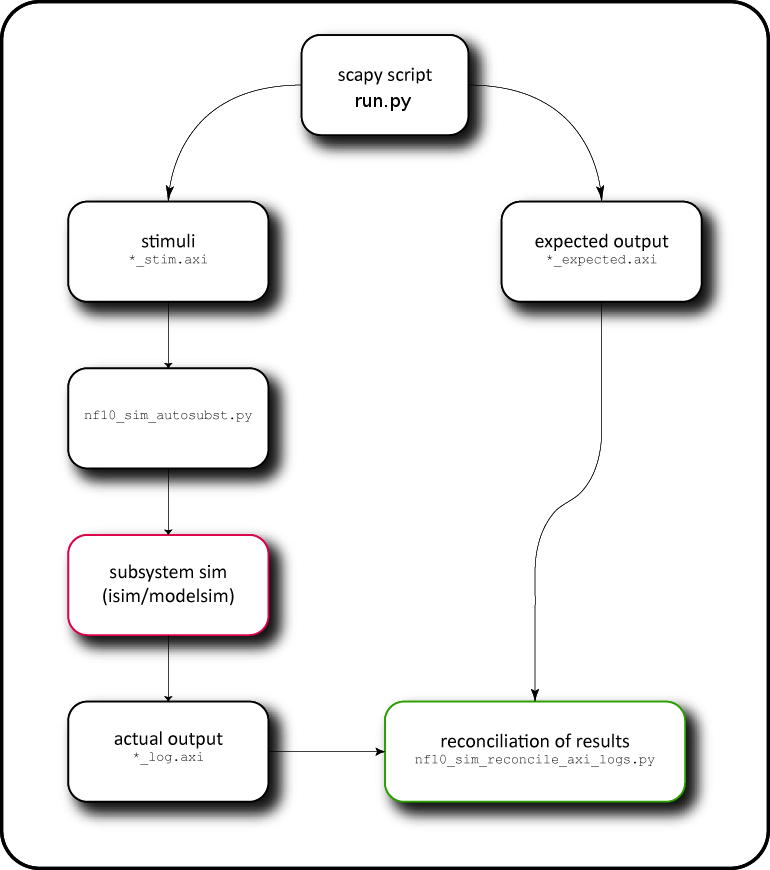
An end-user supplied script, run.py, writes out two sets of AXI Stream files: the stimuli, and the expected results. The project's MHS file is automatically translated into the subsystem simulation by means of the script nf10_sim_autosubst.py. The simulation is run, and the resulting log files are automatically reconciled with the expected output by nf10_sim_reconcile_axi_logs.py.
Instead of specifying times for packet and register operations, the new infrastructure uses a barrier statement for synchronization. The barrier blocks until all expected packets arrive, or it times out, causing the test to fail. This ensures that register operations occur at the correct time relative to the packet operations.
Notes: In order to ensure register reads and writes occur at the correct time relative to packet send and expects, a barrier must be placed between all register operations and packet operations. Both nftest_start and nftest_finish call a barrier, so putting a barrier directly after nftest_start or directly before nftest_finish is redundant.
The new testing infrastructure supports tests running in simulation and multiple hardware configurations by passing arguments to nftest_init.
nftest_init(sim_loop = [], hw_config = None)
For a simulation test, a list of interfaces to put into loopback is passed to the keyword argument sim_loop. For example, to put nf2 and nf3 (ports 3 and 4) into loopback, the argument is nftest_init(sim_loop = ['nf2','nf3']).
The directory structure is as follows (example for reference nic: cd ~/NetFPGA-10G-live/projects/reference_nic/test):
test
├── connections
│   ├── conn
│   └── crossover
├── global
│   └── setup
├── hw_external_crossover
│   └── run.py
├── hw_external_payload
│   └── run.py
├── both_loopback_maxsize
│   └── run.py
├── both_loopback_minsize
│   └── run.py
├── both_loopback_random
│   └── run.py
├── sim_tx_dma
│   └── run.py
├── sim_rx_dma
│   └── run.py
├── sim_txrx_dma
│   └── run.py
connections is the connections folder, where connections files for the project can be placed. A connections file specifies how the network interfaces are physically connected. The connections file is formatted with one connection per line, where the connection is specified by nfX:ethY, denoting that the interface nfX is physically connected to ethY. For example,
nf0:eth1
nf1:eth2
shows that nf0 is connected to eth1 and nf1 is connected to eth2.
In the new python testing infrastructure, simulation and hardware tests have been unified, so a test can be written once and run as either a simulation or hardware test, unless hardware specific functions are needed. Tests should be placed in a project's test directory. Test directories should be named both_{major}{minor} if they can be run in both simulation and hardware, hw{major}{minor} if the test can only be run as a hardware test and sim{major}_{minor} if the test can only be run as a simulation test. Neither major or minor can have underscores in the name, nor can they be blank. For sim_tx_dma, sim_rx_dma or sim_txrx_dma tests, see the Reference Nic Simulation.
run.py is the executable script which runs the test. The run.py calls other functions in the NFTest library. It is important to know what arguments needs to be passed to the run.py along with the tests, so that the system can perform the tests as simulation only, hardware only or both.
Below are the most commonly used methods for writing tests.
Initialization and finalization
- nftest_init - loads and parses the connections file, map file
- nftest_start - starts packet sniffing threads, performs initial reset
- nftest_finish - writes resultant pcap files
Sending and expecting packets
- nftest_send_phy
- nftest_send_dma
- nftest_expect_phy
- nftest_expect_dma
Register operations
- nftest_regwrite
- nftest_regread_expect
Utilities
- nftest_barrier - synchronization tool. waits for expected packets to arrive or times out
- isHW - returns true if test is being run as a hardware test, used to enable a test to have hardware only checks which cannot be done in sim while maintaining support for both hardware and sim
PacketLib - generates packets
- make_IP_pkt ( src_MAC, dst_MAC, EtherType, src_IP, dst_IP, TTL )
- make_ICMP_request_pkt ( src_MAC, dst_MAC, EtherType, src_IP, dst_IP, TTL )
- make_ICMP_reply_pkt ( src_MAC, dst_MAC, EtherType, src_IP, dst_IP, TTL )
- make_ICMP_ttl_exceed_pkt ( src_MAC, dst_MAC, EtherType, src_IP, dst_IP, TTL )
- make_ARP_request_pkt ( src_MAC, dst_MAC, EtherType, src_IP, dst_IP)
- make_ARP_request_pkt ( src_MAC, dst_MAC, EtherType)
- generate_load (length)
The libraries are located in ~/NetFPGA-10G-live/lib/python/NFTest/.
Important:
- By default, the supporting library module axitools.py, required by all sim_Pkt.py scripts, is not installed into python's site-packages directory. It is therefore necessary to add manually the base package's tools/scripts directory to sys.path before importing it. This should be done relative to run.py's path. See the Reference NIC project for an example.
- All IP addresses should be explicitly specified to ensure compatibility with Cygwin platforms.
Packets may be read from a pcap trace using scapy's scapy.utils.rdpcap() function, or else constructed manually from scapy primitives. When constructing packets, bear in mind that scapy does not pad out the packet to Ethernet's minimum length packet, nor does it add a CRC. Unless you explicitly add padding, the timing behaviour seen in simulation will not match timing seen in hardware.
Each packet has several attributes which may be used to control how and when the packet is processed. All are optional.
| Attributes | Description |
|---|---|
| .time | Time (in seconds) at which packet should be injected |
| .tuser | If present, sets the 128-bit TUSER field. Should be a list of 128-bit integers, one for each cycle of the packet. Padded with zeros if shorter. |
| .tuser_sport | If present, overrides the source port field in .tuser. Integer. |
| .tuser_dport | If present, overrides the destination port field in .tuser. Integer. |
See Standard IP Interfaces for the definition of .tuser, in particular the encodings of the source and destination ports. NB: for most designs, setting .tuser_dport is unlikely to have any effect.
An appropriate sequence of packets should each be written out to a suitably named text file using the function axitools.axis_dump():
def axis_dump( packets, f, bus_width, period, tuser_width = 128 ):
where packets is a list of scapy packets, f is an open, writable file handle, bus_width is the width (in bits) of the design's internal data path (32 and 256 for 1G and 10G interfaces respectively), and period is the period (in seconds) of the datapath clock. The clock period is used to determine how long each packet takes to clock through, and thereby what the inter-frame gap should be. tuser_width should be omitted (left at its default of 128 bits), unless your design uses a different width for TUSER.
NB: There is currently no way to inject bubbles within a packet (i.e. cycles where TVALID == 0), although this could be hacked by passing a StringIO buffer to axis_dump(), and manually inserting bubbles (* n) before writing the text out.
The filenames to use correspond with the instance names of the pcores that are replaced by nf10_sim_autosubst.py, and should be retrieved from the output of that script.
For the sake of performance — rather than simulate the complete design, including the 10G MACs, PCI Express end-point, and the respective testbench peers required to drive them — the tool nf10_sim_autosubst.py automatically replaces the pcores that represent these interfaces to the external world with instances of nf10_axis_sim_stim and nf10_axis_sim_record, respectively one for each of the AXI4 Stream master and slave ports of those pcores.
In principle, nf10_sim_autosubst.py may be run without command-line arguments, but most projects will require additional information that can't be inferred automatically:
- Where a clock or reset for a given pcore is ambiguous (or can't be inferred by name), the correct net can be forced using the --clock (-c) or --reset (-r) flags. Overrides may be specified by pcore (all instances), or specific instances by instance name.
- The --xlate flag can be used to rename whole nets (i.e. everywhere in the MHS file), which may be useful where a pcore sources a clock, which would otherwise be sourceless after it is replaced.
- When an output filename is not specified, nf10_sim_autosubst.py will rewrite the input MHS file in-place. The --undo flag will revert the changes back to the synthesizable design.
- By default, the pcores replaced are nf10{10g,1g}interface and nf10_oped. You can specify additional target pcores for replacement on the command line, optionally suppressing the default targets with the --no-default-targets flag.
TDATA width is automatically inferred (and set on simulation pcore instances) by looking at the pcore instances on both ends of each AXI Stream link for the parameters C_M/S_AXIS_DATA_WIDTH (as appropriate). If none are found, then no width parameter is specified for the simulation pcore. All the standard pcores supplied in the base package share a default of 256 bits. As long as your pcores also use the same default width, or at least always explicitly specify TDATA width, there should be no mismatches.
When nf10_sim_autosubst.py is run, it will print a report of which instances of which pcores have been replaced, which clock and reset nets have been used, and the associated AXI filenames. As long as instance names remain unchanged, the results will be consistent. The run.py script should at least create every file ending in _stim.axi (or the simulation will fail) and files ending in _expected.axi for every file ending in _log.axi (or the results won't be checked.)
NB: The python module mhstools, upon which nf10_sim_autosubst.py depends for parsing and rewriting MHS files, is available for end-user use if of any value. There is also some potentially useful code for handling and resolving pcore libraries in chk_pcore_versions.py.
The script nf10_sim_reconcile_axi_logs.py is a generic tool which, for every AXI trace _expected.axi, attempts to load the corresponding AXI log (_log.axi) using axitools.axis_dump(). It then does a bit-wise comparison between actual and expected packets, and reports expected and actual packet counts, along with a simple pass/fail result. For the benefit of regression tests, a fail condition is signalled with a shell return code of 1.
NB: Packet arrival time, any bubbles within a packet (i.e. cycles where TVALID == 0), and TUSER values are ignored altogether.
Before running the simulation, Do not forget to:
- source the Xilinx tool: source /{yourXilinxpath}/setting64.sh
- make sure the bashrc_addon_NetFPGA_10G is updated in your system. Check if all variables are set in the right path. Try to run echo $NF_ROOT and echo $NF_DESIGN_DIR and check if your directories are correct.
- check if the pyhton files are in the proper modes (executables). If not when you run the simulation tests, it will give you a "permission denied" error (change the permissions with: chmod +x {filename}).
- Make sure you clone the latest version of the NetFPGA package. Please ensure that you have the necessary packages installed. The current simulation and hardware testing infrastructure is Python based.
git clone https://github.com/NetFPGA/NetFPGA-10G-live.git
Note: Update your bashrc with the bashrc_addon_NetFPGA provided in your clone.
- Do a make cores inside ~/NetfPGA-10G-live/ directory.
# cd $NF_ROOT
# make cores
- Do a make inside ~/NetfPGA-10G-live/ directory for the HW Test library that creates a shared library which is used by the python infrastructure to access the registers.
# make hwtestlib
You can remove the files by doing make hwtestlibclean
- Tests are run using the nf_test.py command, inside the ~/NetfPGA-10G-live/tools/bin directory. When running a test, the test mode (sim or hw) must be specified. Optional parameters include
--major <string>
--minor <string>
For instance:
cd ~/NetFPGA-10G-live/tools/bin
./nf_test.py sim --major loopback --minor minsize --isim
For a complete list of arguments, call ./nf_test.py --help
- The simulation includes two simulation targets:
-
./nf_test.py sim --major .... --minor .... --isim will run a non-interactive simulation, controlled by hw/nf10/noninteractive_sim.tcl, with results checked automatically by nf10_sim_reconcile_axi_logs.py.
-
./nf_test.py sim --major .... --minor .... --isim --gui will start an interactive session under the control and inspection of the user. nf10_sim_reconcile_axi_logs.py is still run, but not until after the GUI closes. The user may, of course, manually run this script before then.
-
If you want to clean your directory from the simulation results, do a make simclean inside the ~/NetFPGA-10G-live/projects/{your_project}/test directory
The pcore nf10_axi_sim_transactor is provided for performing simple register reads and writes via the AXI interconnect. It is written to be ignored during synthesis, and is therefore safe to include in all designs permanently.
Its input file, reg_stim.axi, written in the same AXI grammar used for AXI4 Stream simulations, it is written from simLib.py script. A brief summary of its features:
- Blank lines are ignored, and comments may be included (demarcated by #)
- Each line represents a single AXI4 Lite transaction. The exact number of cycles required depends on the configuration of the AXI interconnect and how quickly AXI4 Lite slaves respond to requests.
- Since it is technically possible to commit a read and a write operation in the same cycle, the grammar reflects this. Whether this is actually possible or not depends on how the AXI Interconnect component is configured. The more usual case is that one or the other (read or write) will be a NO-OP (represented by dashes [-]).
- The transactor can be asked to wait until an operation completes (indicated by a period [.], the usual case), or it may be allowed to proceed to the next transaction straight away (indicated by a comma [,]).
Be sure to read the AXI transaction grammar specification for the complete details and limitations.
#
# Example AXI4-Lite stimuli - reg_stim.axi
#

# WRITE
77600000, deadc0de, f, -.
77600004, acce55ed, f, -.
77600008, add1c7ed, f, -.
7760000c, cafebabe, f, -.

# READ
-, -, -, 77600000.
-, -, -, 77600004.
-, -, -, 77600008.
-, -, -, 7760000c.
A log file reg_stim.log is written by the transactor, which may be inspected visually, or parsed and checked by a script.
7A000000 <- DEADC0DE (OKAY) # 1325 ns
7A000004 <- ACCE55ED (OKAY) # 1385 ns
7A000008 <- ADD1C7ED (OKAY) # 1445 ns
7A00000C <- CAFEBABE (OKAY) # 1505 ns
7A000000 -> 00000000 (OKAY) # 1575 ns
7A000004 -> 00000000 (OKAY) # 1635 ns
7A000008 -> 00000000 (OKAY) # 1695 ns
7A00000C -> 00000000 (OKAY) # 1755 ns
The fields are: address, direction (<- and -> for write and read respectively), data, (result), and the moment in simulation time when the read or write result is returned is noted as a comment.