Clarity needed for Alignment Cant axis of rotation #160
Comments
|
Looks like I can answer my own question based on discussion in the referenced thread. The geometry representation can stand on its own and does not require anything from the business logic. The other two points still stand - another diagram is required to describe rotation about centerline and both diagrams need updated to dimension CantLeft and CantRight that are contained in the business logic. Which then also means another normative rule in the ALA series is required to confirm that the point of rotation described by the representation matches what is described by the values of CantLeft and CantRight in the business logic. |
|
Revised diagrams: ROTATION ABOUT RAILHEAD ROTATION ABOUT CENTERLINE |


|
In practice, I think you are right that the point of rotation is at one of the rail heads or at the center point between. However, the semantic and geometry definitions could be used for rotation about any point. Here is a quick sketch to illustrate what I mean.
LeftCant, RightCant, and Railhead Distance define slope and point of rotation |

Problem
Ref buildingSMART/IFC4.3.x-sample-models#23
As I see it there are four variables related to fully describing cant:
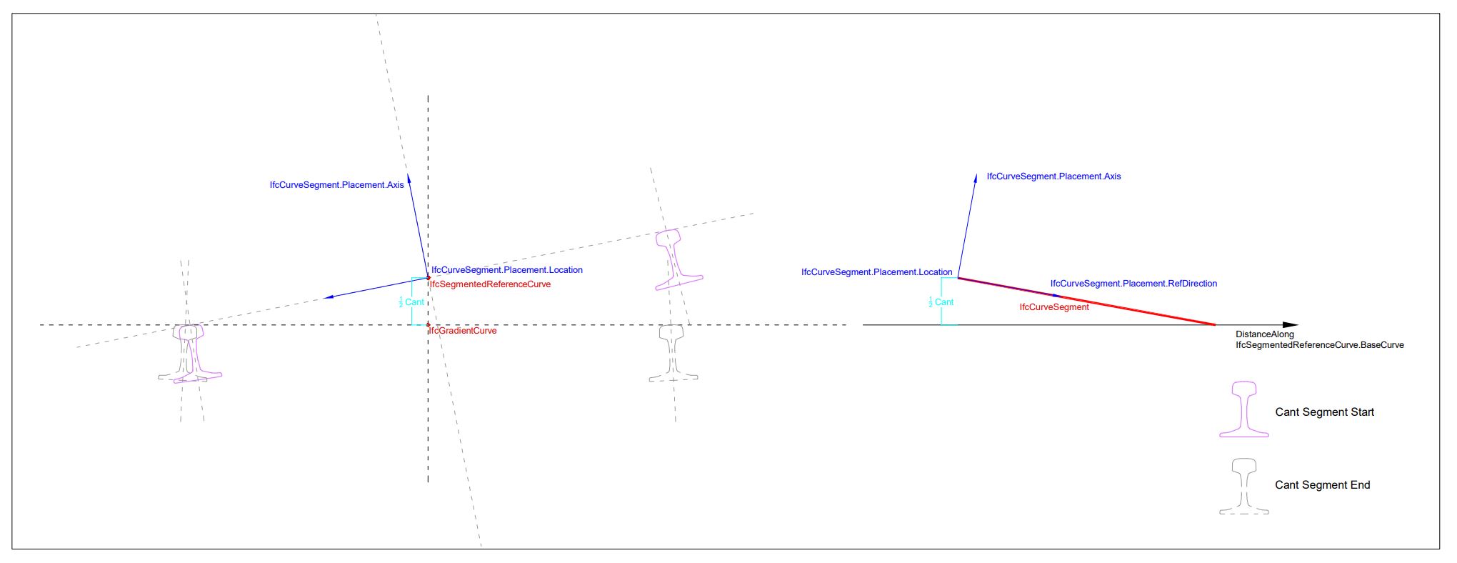
Figure 8.9.3.62.A in the docs for IfcSegmentedReferenceCurve illustrates these relationships when the low rail is the point of rotation:
There is no corresponding figure to illustrate how rotation about centerline is to be defined.
Solution(s)
Another graphic illustration for rotation about centerline of rail is needed.
Require schema changes?
✓noRequire documentation changes?
✓yesRule required
✓other normative rule: a normative check of the IFC Validation Service. Every IFC file must pass this checkMy hypothesis is that business logic - specifically IfcAlignmentCantSegment.DesignParameters - must be provided in addition to the IfcCurveSegment representation entity. If true then this should be enforced by a normative rule.
The text was updated successfully, but these errors were encountered: