Working with ATtinyx61 #43
Conversation
Had to merge PCINT0_vect and PCINT1_vect into the single available
interrupt callback, PCINT_vect. Added an initialization method
to clear out interrupts in both PCMSK0 and PCMSK1 on ATtinyx61 as
interrupts on all pins are enabled by default. The split between
PCIE0 and PCIE1 isn't even so a manual range check is done so that
PCIE0 is only used on port 1 for the first 4 pins.
|
Wait waaat? This looks super weird. I've seen the datasheet and it seems to be super weird. However I am not sure if your solution will properly work. I think you are only capturing the states of 8 bits, but you code can be used for way more pins. That looks incorrect. Now my big question is: If there is only one interrupt vector for two ports, how can you tell which port caused the interrupt? And furthermore why did the code compile until now? It think it should not even compile. I might missunderstand, but I think we need to dig deeper into that one. Thanks for sharing your solution. |
|
I don't think there's anything that would cause it to not compile previously but the ISR methods would not actually connect to anything. They would end up no different than any other user created method. In the interrupt vector you can still examine the separate PCINT registers to determine which set of pins caused the interrupt. There's just no real shortcut anymore, you have to examine both registers. |
src/PinChangeInterrupt.h
Outdated
| @@ -107,6 +107,12 @@ PinChangeInterruptEventPCINT ## pcint PCINT_MACRO_BRACKETS | |||
| #error MCU has no such a register | |||
| #endif | |||
|
|
|||
| #if defined(__AVR_ATtiny261__) || defined(__AVR_ATtiny461__) || defined(__AVR_ATtiny861__) | |||
| #define initPinChangeInterrupt() PCMSK0 = 0; PCMSK1 = 0 | |||
There was a problem hiding this comment.
The x61 starts with all interrupts enabled (PCMSK0 == PCMSK1 == 0xff) so to get the same behaviour as the other versions I start by turning them all off.
There was a problem hiding this comment.
Why is that so? Is that an issue of the attiny core or the attiny itself? That sounds super strange!
There was a problem hiding this comment.
Rereading it now it's not all it's just 11 of them. If you look in the data sheet in 9.3.4 and 9.3.5 it shows the initial state of the registers which has PCINT8:15, PCINT3, and PCINT6:7 enabled.
There was a problem hiding this comment.
WTF, please stop! Why are you using such an MCU? XD
Maybe we already missed that for other attinys as well? I am not sure if it will impact the behavior if all pins are just enabled.
There was a problem hiding this comment.
I excluded the if (pcintPort ==1) check for PCIE1 because I think it makes more sense to always clear the entire set for consistent functionality. I can add the check in if you prefer though.
There was a problem hiding this comment.
Well, that is a good point. But if you remove that if, you can also remove the other larger if above. When the enable bit is not set, always clear the related PCMSK's. That is more straightforward and will always clear both, if both are disabled.
For example if you are using only PCINT 0-7, then on each enable PCMSK1 (half of it) will be cleared. So we can chose between a more correct behavior or a more efficient behavior. I guess removing the if will cause in less flash usage. can you please verify? Since that fix is somewhat hacky anyways I'd also be open for your solution and just always clear it (when PCIE is not yet set)
There was a problem hiding this comment.
For example if you are using only PCINT 0-7, then on each enable PCMSK1 (half of it) will be cleared.
Not on each enable, just the first. Unless you disable all interrupts for PCIE1 between the enables.
Unless I'm missing something it seems like your method would mean that if a user enabled an interrupt on one of the PCINT 0-7 pins but was doing something else on PCINT 12-15 then the interrupt vector would be called every time something happened on PCINT12-15, even though the user doesn't want to use them.
There was a problem hiding this comment.
To clarify: This would be the most compact code:
// Special case for Attiny x61 where PCMSK0 and PCMSK1 registers
// have initial values of 1 for some reason.
// See datasheet section 9.3.4 and 9.3.5
// https://ww1.microchip.com/downloads/en/devicedoc/atmel-2588-8-bit-avr-microcontrollers-tinyavr-attiny261-attiny461-attiny861_datasheet.pdf
#if defined(GIMSK) && (defined(__AVR_ATtiny261__) || defined(__AVR_ATtiny461__) || defined(__AVR_ATtiny861__))
#if (PCINT_USE_PORT1 == true)
  // PCIE0 case
  if (!(GIMSK & (1 << PCIE0))) {
    // Clear PCINT11:8
    PCMSK1 &= ~0x0F;
  }
#endif

  // PCIE1 case
  if (!(GIMSK & (1 << PCIE1))) {
#if (PCINT_USE_PORT1 == true)
    // Clear PCINT15:12
    PCMSK1 &= ~0xF0;
#endif
    // Clear PCINT7:0
    PCMSK0 = 0x00;
  }
#endif
Now lets say the user enables all PCINT0-7 pins. Then he disables them again. On each disable PCMSK1 &= ~0x0F; gets called, as PCIE0 is not set. It should not matter, as all interrupts are disabled anyways.
Now the question is do we want:
- less size, but wonky logic
- more size, clean logic
There was a problem hiding this comment.
I made this change. I think in many cases I may have left the checks in so that I'm not updating something unnecessarily but I don't suspect that will make a difference here so this is less overhead.
|
Now looking closer at this PR it is a huge WTF, but looks very "clean" (as clean as it can get) to support all pins for this attiny. Now beside the fact that this PR works, did you ever think of only enabling PCINT 0-7? Cause the other PCINTs are on pins used for clock, int0, reset etc, which are very likely never used anyways. So it might make sense to remove that boilerplate, which will cause a lot faster interrupt handling and less flash size. |
Rename PCINT_COMBINE_PORT01 to PCINT_COMBINE_PORT0_PORT1 to
be more explicit with what is being combined.
Always check if PORT1 is enabled along with the combined
ports for completeness.
When enabling PCIE0 and PCIE1 on x61 devices check if PORT1
should be used so that it can still be enabled/disabled
separately from PORT0.
Added logic to disable the interrupts entirely if all pin change
interrupts are disabled on either port. Allows PORT1 to be disabled
separately from PORT0.
I considered this but wanted to make this as generic as possible, which meant allowing all pins to be used. I've tried to make the logic in the new commits so that it will allow PORT 1 to be disabled but left it always enabled on x61 devices. |
Catch initialization conditions in enablePinChangeInterruptHelper
instead of requiring a separate initialization method.
Increase consistency and use true while defining
PCINT_COMBINE_PORT0_PORT1 instead of 1. Shouldn't affect uses
elsewhere.
src/PinChangeInterrupt.cpp
Outdated
| if(disable) | ||
| { | ||
| #ifdef PCICR | ||
| PCICR &= ~(1 << (pcintPort + PCIE0)); | ||
| #elif defined(GICR) /* e.g. ATmega162 */ | ||
| GICR &= ~(1 << (pcintPort + PCIE0)); | ||
| // if PORT1 is disabled on a x61 device this will handle the backwards PCIE definitions | ||
| #elif defined(GIMSK) && (defined(__AVR_ATtiny261__) || defined(__AVR_ATtiny461__) || defined(__AVR_ATtiny861__)) |
There was a problem hiding this comment.
I think the whole commit for disabling needs a rework. I think we only need a similar check to the enabling at this location, just for disabling. No need for this complicated logic. It looks error-prone.
There was a problem hiding this comment.
I'll take a look again tomorrow but I think PCIE1 working with both ports requires the check to be a bit more complicated. The if will always need more checks than just PCMSK0 or PCMSK1 being 0 and inside the if (disable) block you would need to duplicate the pcintPort and pcintMask check.
There was a problem hiding this comment.
This should do it:
#ifdef PCINT_COMBINE_PORT0_PORT1
#if defined(GIMSK) && (defined(__AVR_ATtiny261__) || defined(__AVR_ATtiny461__) || defined(__AVR_ATtiny861__))
    // This is a special case for Attiny x61 series which was very weird PCINT mapping.
    // See datasheet section 9.3.2:
		// http://ww1.microchip.com/downloads/en/devicedoc/atmel-2588-8-bit-avr-microcontrollers-tinyavr-attiny261-attiny461-attiny861_datasheet.pdf
#if (PCINT_USE_PORT1 == true)
    if (pcintPort == 1 && pcintMask < (1 << 4)) {
        // PCINT11:8 will be disabled with PCIE0
				if (!(PCMSK1 & 0x0F)) {
					GIMSK &= ~(1 << PCIE0);
				}
    }
    else {
        // PCINT7:0 and PCINT15:12 will be disabled with PCIE1
				if (!PCMSK0 && !(PCMSK1 & 0xF0)) {
#else
				if (!PCMSK0) {
#endif
					GIMSK &= ~(1 << PCIE1);
				}
#if (PCINT_USE_PORT1 == true)
    }
#endif
#else
#error MCU has no such a register
#endif

	// Always return, as we are using a different logic for disabling the interrupts.
	return;
#endif // ifdef PCINT_COMBINE_PORT0_PORT1
Place it above the if(disabled) section. It would be super nice, if you can give my code a review and also a real test on the device itself, as I cannot check. I did not even check if it compiles, as I've written it just in the editor.
There was a problem hiding this comment.
I had to also do a bit of logic earlier to check the top and bottom half of PCMSK1 separately when deciding if disable should be set. If they are always checked together then there are cases where having interrupts enabled on multiple pins will stop PCIE0 and PCIE1 from being cleared when only one of the interrupts is disabled. And all code has been compiled and uploaded to a ATTINY861 with some interrupt tests using a button and some LEDs.
There was a problem hiding this comment.
I think you missunderstood my code. Now you have duplicated code. Why are you using the disabled flag at all? It does not really help in that special case. Thatswhy I suggested to ignore that and place my code above the if (disabled) check. Or is there any problem with that logic? I can imagine that it is faster and consumes less flash memory.
There was a problem hiding this comment.
You're correct, I completely misread your comment. I've updated disablePinChangeInterruptHelper to remove the disable block for this case and just always check if the masks are empty.
The initialization method has been removed so the keyword is
no longer required.
Move some of the logic for determining when an interrupt flag
can be cleared from the switch statement to the if (disabled)
at the end.
The count of the available ports was incorrect because of the
change in interrupt vector names from other versions causing
getArrayPosPCINT to always return 0. Add in special cases for
checking PORT0 and PORT1.
Remove the need for the disable flag and directly check the
status of the masks instead.
When the user is enabling interrupts always clear the interrupt
mask if the pin change interrupt flag is not yet set. This will
cause redundant clears of the registers but removes some of the
overhead of checking which pins the user is attempting to set.
| @@ -371,12 +371,14 @@ Serial.println(); | |||
| // Hardware Definitions | |||
| //================================================================================ | |||
|
|
|||
| #if defined(PCINT0_vect) | |||
| //special case for the x61 where a single interrupt vector is used for multiple ports | |||
| #if defined(PCINT0_vect) || (defined(PCINT_vect) && (defined(__AVR_ATtiny261__) || defined(__AVR_ATtiny461__) || defined(__AVR_ATtiny861__))) | |||
There was a problem hiding this comment.
What about placing this last?
// Special check for combined ports, such as on Attiny x61
#if defined(PCINT_vect)
#ifdef PCINT_COMBINE_PORT0_PORT1
#define PCINT_HAS_PORT0 true
#define PCINT_HAS_PORT1 true
#else
#error Unknown Combined Port Configuration
#endif
#endif
This way it is more flexible.
I am also wondering if we can automate combined port detection by using #if defined(PCINT_vect) maybe? But maybe we should not overcomplicate things.
There was a problem hiding this comment.
I wasn't sure whether PCINT_vect comes up anywhere else currently or might in the future that would make this check incorrect. The only reference I can find to it on other chips is for the ATtiny2313 but I'm not sure that reference is correct.
There was a problem hiding this comment.
Well if it comes up, the code compilation will fail. That is good, so I can fix the issue later on. I also think it would be a good idea to fail like this, as this gives us better detection of new, unsupported MCUs. Meaning if it uses such weird port combination we will be notified faster with this error message.
Speaking of ATtiny2313, I remember that I had lots of problems with this MCU. I might need to revisit that. But that for another PR.
There was a problem hiding this comment.
I just checked the Attiny 2313, and I am wondering why it works with ISR(PCINT0_vect)? It has no such interrupt vector (following the datasheet).
|
Since I've merged the other PR you need to resolve some conflicts. If you are not very familiar with git, you can continue to work on this PR like you are used to, and I can fix that for you, once it is ready to merge. |
| @@ -247,9 +285,31 @@ void disablePinChangeInterruptHelper(const uint8_t pcintPort, const uint8_t pcin | |||
| // if that's the last one, disable the interrupt. | |||
| if (*(&PCMSK + pcintPort) == 0) { | |||
| disable = true; | |||
| } | |||
There was a problem hiding this comment.
That bracket is missing. I guess the code will not compile now.
| #if (PCINT_USE_PORT1 == true) | ||
| } | ||
| #endif | ||
| #else |
There was a problem hiding this comment.
We do not need this else path, if you add the return statement, that I've added in my original code snipped. That would be much clearer to separate this special use case.
Updates for issue #39, tested working on an ATtiny861.
Had to merge PCINT0_vect and PCINT1_vect into the single available interrupt callback, PCINT_vect. I did this by merging the PCINT1 code into PCINT0 and only enabling it on the x61. Probably not the best way to do this as it duplicates code between PinChangeInterrupt0.cpp and PinChangeInterrupt1.cpp.
Added an initialization method to clear out interrupts in both PCMSK0 and PCMSK1 on ATtinyx61 as interrupts on all pins are enabled by default. It's really just a #define and does nothing on other devices.
The split between PCIE0 and PCIE1 isn't even, 0 does PCINT 8-11 and 1 does PCINT 0-7 and 12-15. In enablePinChangeInterruptHelper a manual range check is done so that PCIE0 is only used for the first 4 pins of port 1.
I left the digitalPinToPCINT method as is which means it will still not work. I tested using the pin definitions from ATtinyCore (PIN_PA0, ..., PIN_PB7) which can be used as inputs to attachPinChangeInterrupt directly.
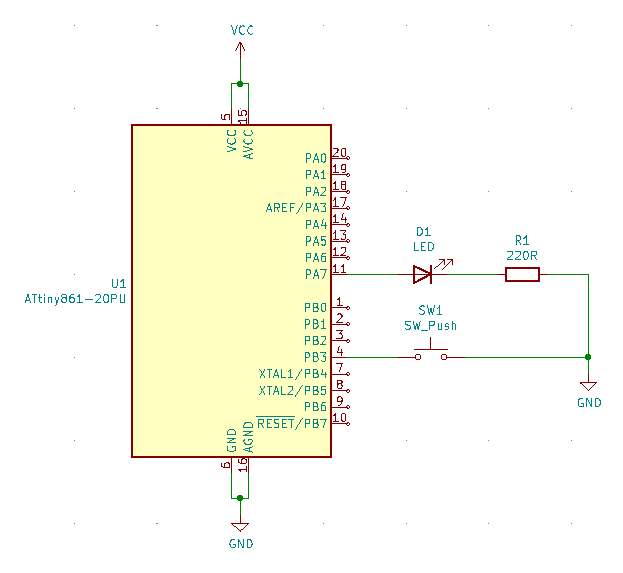
My working test code:
With this simple circuit: