This is the Nuvoton RunBMC System layer. The NPCM750 is an ARM based SoC with external DDR RAM and supports a large set of peripherals made by Nuvoton. More information about the NPCM7XX can be found here.
- Working with openbmc master branch
This layer depends on:
  URI: github.com/NTC-CCBG/openbmc.git
  branch: buv-dev
Please submit any patches against the meta-runbmc-nuvoton layer to the maintainer of nuvoton:
- Brian Ma, [email protected]
- Jim Liu, [email protected]
We have runbmc card on server Olympus, so we make a BUV carried board.
The BUV board can plug in the runbmc card.
- reference with Rework for buv
- Dependencies
- Contacts for Patches
- Rework for buv
- Features of NPCM750 RunBMC BUV
- IPMI Commands Verified
- DCMI Commands Verified
- Image Size
- Modifications
This is a Virtual Network Computing (VNC) server programm using LibVNCServer.
- Support Video Capture and Differentiation(VCD), compares frame by hardware.
- Support Encoding Compression Engine(ECE), 16-bit hextile compression hardware encoding.
- Support USB HID, support Keyboard and Mouse.
Source URL
How to use
- Power on the Nuvoton RunBMC BUV
- Make sure the network is connected with your workstation.
- Launch a browser in your workstation and you will see the entry page.
/* BMCWeb Server */ https://<poelg ip> - Login to OpenBMC home page
Username: root Password: 0penBmc - Navigate to OpenBMC WebUI viewer
Server control -> KVM
Performance
- Host OS: Windows Server 2012 R2
| Playing video: AQUAMAN | Real VNC viewer | noVNC viewer |
|---|---|---|
| Host Resolution | FPS | FPS |
| 1024x768 | 25 | 8 |
| 1280x1024 | 20 | 4 |
| 1600x1200 | 14 | 3 |
| Scrolling bar: Demo video | Real VNC viewer | noVNC viewer |
|---|---|---|
| Host Resolution | FPS | FPS |
| 1024x768 | 31 | 15 |
| 1280x1024 | 24 | 12 |
| 1600x1200 | 20 | 7 |
The preferred settings of RealVNC Viewer
Picture quality: Custom
ColorLevel: rgb565
PreferredEncoding: Hextile
Maintainer
- Jim Liu & Brian Ma
The Serial over LAN (SoL) console redirects the output of the server’s serial port to a browser window on your workstation.
This is a patch for enabling SOL in phosphor-webui on Nuvoton's NPCM750.
The patch provides the obmc-console configuration.
How to use
-
Setup serial console in Ubuntu host
- reference: Ubuntu 16.04: GRUB2 and Linux with serial console
- Set value as following in /etc/default/grub
GRUB_CMDLINE_LINUX="console=tty console=ttyS1,57600"- Then make grub.cfg
sudo grub-mkconfig -o /boot/grub/grub.cfg -
Run SOL:
- Launch a browser in your workstation and navigate to https://${BMC_IP}
- Bypass the secure warning and continue to the website.
- Enter the BMC Username and Password (defaults: root/0penBmc).
- You will see the OpenBMC management screen.
- Click
Server controlat the left side of the OpenBMC management screen. - A
Serial over LAN consolemenu item prompts then and click it. - Power on host server.
- A specific area will display the host ttyS1 that user can operate host OS.
Maintainer
- Jim Liu & Brian Ma
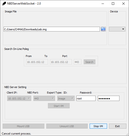
Virtual Media (VM) is to emulate an USB drive on remote host PC via Network Block Device(NBD) and Mass Storage(MSTG).
Source URL
- https://github.com/Nuvoton-Israel/openbmc/tree/runbmc/meta-phosphor/nuvoton-layer/recipes-connectivity/jsnbd
- https://github.com/Nuvoton-Israel/openbmc-util/tree/master/virtual_media_openbmc2.6
How to use
-
Clone a physical USB drive to an image file
-
For Linux - use tool like dd
dd if=/dev/sda of=usb.img bs=1M count=100bs here is block size and count is block count.
For example, if the size of your USB drive is 1GB, then you could set "bs=1M" and "count=1024"
-
For Windows - use tool like Win32DiskImager.exe
NOTICE : A simple *.iso file cannot work for this.
-
-
Enable Virtual Media
2.1 VM-WEB
-
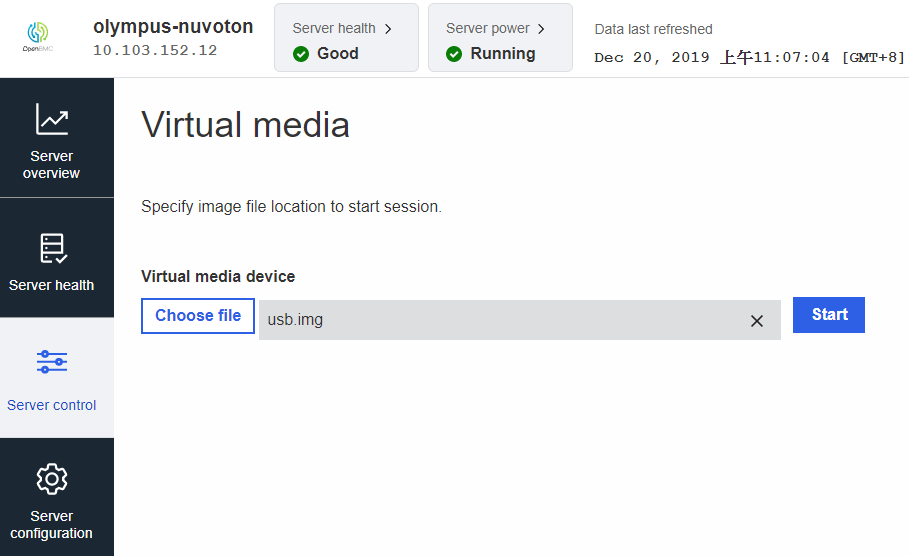
Login and switch to webpage of VM on your browser
https://XXX.XXX.XXX.XXX/#/server-control/virtual-media -
Operations of Virtual Media
- After
Choose File, clickStartto start VM network service - After clicking
Startand connect J2009 to your HOST, you will see a new USB device on HOST OS - If you want to stop this service, just click
Stopto stop VM network service.
- After
-
Maintainer
- Jim Liu & Brian Ma
This is a secure flash update mechanism to update BMC firmware via WebUI.
Source URL
How to use
-
Update firmware via WebUI
-
Upload update package from web UI, then you will see
ActivateIf you select activate, then you will see activation dialog at item 2
DeleteIf you select delete, then the package will be deleted right now
-
Confirm BMC firmware file activation
ACTIVATE FIRMWARE FILE WITHOUT REBOOTING BMCIf you select this, you need to reboot BMC manually, and shutdown application will run update script to flash image into SPI flash
ACTIVATE FIRMWARE FILE AND AUTOMATICALLY REBOOT BMCif you select this, BMC will shutdown right now, and shutdown application will run update script to flash image into SPI flash
-
-
Update firmware via Redfish
We can update BMC firmware via REST API provided by Redfish. The firmware will apply immediately after uploaded without any confirmation by default. The following command shows how to using curl command upload BMC firmware.
curl -X POST -H "x-auth-token: ${token}" --data-binary obmc-phosphor-image-buv-runbmc-20200814010351.static.mtd.tar https://${BMC_IP}/redfish/v1/UpdateService${token} is the token value come from login API, read more information from REST README
Maintainer
- Jim Liu & Brian Ma
We provided three ways that user can synchronize the BMC time from network or host.
Network Time Protocol (NTP) is a networking protocol for clock synchronization between computer systems over packet-switched, variable-latency data networks.
systemd-timesyncd is a daemon that has been added for synchronizing the system clock across the network. It implements an SNTP (Simple NTP) client. This daemon runs with minimal privileges, and has been hooked up with systemd-networkd to only operate when network connectivity is available.
The modification time of the file /var/lib/systemd/timesync/clock indicates the timestamp of the last successful synchronization (or at least the systemd build date, in case synchronization was not possible).
Source URL
- https://github.com/openbmc/phosphor-time-manager
- https://github.com/systemd/systemd/tree/master/src/timesync
-
Enable NTP by Web-UI
Server configuration->Date and time settings -
Enable NTP by command
timedatectl set-ntp truetimedatectl result will show systemd-timesyncd.service active: yes
If NTP is Enabled and network is Connected (Using eth1 connect to router), we will see the item systemd-timesyncd.service active is yes and System clock synchronized is yes. Thus, system time will sync from NTP server to get current time.
-
Get NTP status
timedatectlLocal time: Mon 2018-08-27 09:24:51 UTC
Universal time: Mon 2018-08-27 09:24:51 UTC
RTC time: n/a
Time zone: n/a (UTC, +0000)
System clock synchronized: yes
systemd-timesyncd.service active: yes
RTC in local TZ: no -
Disable NTP
timedatectl set-ntp falsetimedatectl result will show systemd-timesyncd.service active: no
-
Using Local NTP server Configuration
When starting, systemd-timesyncd will read the configuration file from /etc/systemd/timesyncd.conf, which looks like as below: >[Time]
>#NTP=
>#FallbackNTP=time1.google.com time2.google.com time3.google.com time4.google.comBy default, systemd-timesyncd uses the Google Public NTP servers **time[1-4].google.com**, if no other NTP configuration is available. To add time servers or change the provided ones, **uncomment** the relevant line and list their host name or IP separated by a space. For example, we setup NB windows 10 system as NTP server with IP **192.168.1.128** >_[Time] >**NTP=192.168.1.128** >\#FallbackNTP=time1.google.com time2.google.com time3.google.com time4.google.com_ -
BMC connect to local NTP server of windows 10 system
Connect to NB through eth1 EMAC interface, and set static IP 192.168.1.15ifconfig eth1 up ifconfig eth1 192.168.1.15Note: Before that you need to setup your NTP server (192.168.1.128) on Windows 10 system first
Modify /etc/systemd/timesyncd.conf file on BMC as we mentioned >[Time]
>NTP=192.168.1.128Re-start NTP to make effect about our configuration change
systemctl restart systemd-timesyncd.serviceCheck status of NTP that show already synced to our local time server
systemctl status systemd-timesyncd.service -l --no-pagerStatus: "Synchronized to time server 192.168.1.128:123 (192.168.1.128)."
Verify Web-UI
Server overview->BMC timewhether sync from NTP server as same as timedatectl. (Note: timedatectl time zone default is UTC, thus you will find the BMC time is UTC+8)timedatectlLocal time: Thu 2018-09-06 07:24:16 UTC
Universal time: Thu 2018-09-06 07:24:16 UTC
RTC time: n/a
Time zone: n/a (UTC, +0000)
System clock synchronized: yes
systemd-timesyncd.service active: yes
RTC in local TZ: no -
TimeZone
According OpenBMC current design that only support UTC TimeZone now, we can use below command to get current support TimeZone on BMCtimedatectl list-timezones
Maintainer
- Jim Liu & Brian Ma
Intel PCH provides read commands that BMC get PCH time over i2c.
If BMC is connected to PCH, you can use this feature to hanle BMC time.
How to use
- Please check the i2c bus and slave address
- The serivce will auto sync pch time during openbmc startup.
Maintainer
- Jim Liu & Brian Ma
Intel Node Manager is synchronizing periodically its internal clock with system RTC.
It also provides a get sel command that BMC can get time over IPMB interface.
How to use
- Please follow Host Power Budget Control to setup IPMB interface.
- The serivce will auto get time via get sel time command during openbmc startup.
Maintainer
- Jim Liu & Brian Ma
phosphor-hwmon daemon will periodically check the sensor reading to see if it exceeds lower bound or upper bound . If alarm condition is hit, the phosphor-sel-logger handles all sensor events to add new IPMI SEL records to the journal, phosphor-host-ipmid will convert the journal SEL records to IPMI SEL record format and reply to host.
Source URL
- https://github.com/NTC-CCBG/openbmc/tree/buv-dev/meta-evb/meta-evb-nuvoton/meta-buv-runbmc/recipes-phosphor/configuration
- https://github.com/NTC-CCBG/openbmc/tree/buv-dev/meta-evb/meta-evb-nuvoton/meta-buv-runbmc/recipes-phosphor/ipmi
- https://github.com/NTC-CCBG/openbmc/tree/buv-dev/meta-evb/meta-evb-nuvoton/meta-buv-runbmc/recipes-phosphor/sensors
How to use
-
Configure sensor
-
Add Sensor Configuration File
Each sensor temperature, adc, fan, peci and power has a hwmon config file and ipmi sdr config file that defines the sensor name and its warning or critical thresholds. These files are located under recipes-phosphor/sensors/phosphor-hwmon%/obmc/hwmon/apb/ and recipes-phosphor/configuration/olympus-nuvoton-yaml-config/olympus-nuvoton-ipmi-sensors.yaml.
Below is hwmon config for a LM75 sensor on BMC. The sensor type is temperature and its name is bmc_card. It has warning and critical thresholds for upper and lower bound.
LABEL_temp1 = "bmc_card"
WARNHI_temp1 = "110000"
WARNLO_temp1 = "5000"
CRITHI_temp1 = "115000"
CRITLO_temp1 = "0"
Below is ipmi sdr config for a LM75 sensor on BMC.
1:
  entityID: 0x07
  entityInstance: 1
  sensorType: 0x01
  path: /xyz/openbmc_project/sensors/temperature/bmc_card
  sensorReadingType: 0x01
  multiplierM: 1
  offsetB: 0
  bExp: 0
  rExp: 0
  scale: -3
  unit: xyz.openbmc_project.Sensor.Value.Unit.DegreesC
  mutability: Mutability::Write|Mutability::Read
  serviceInterface: org.freedesktop.DBus.Properties
  readingType: readingData
  sensorNamePattern: nameLeaf
  interfaces:
    xyz.openbmc_project.Sensor.Value:
      Value:
        Offsets:
          0xFF:
            type: int64_t
-
-
Monitor sensor and events
-
Using WebUI
In
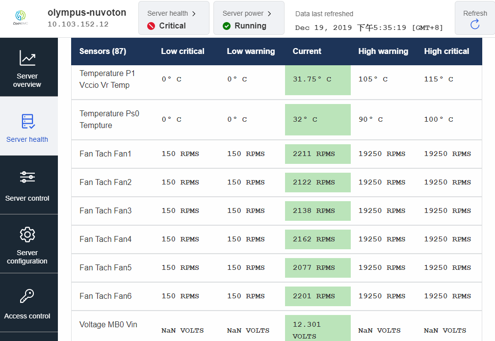
Sensorspage of WebUI, the sensors reading will show as below.In
System logpage of WebUI, the sensors event will show as below. -
Using IPMI
Use IPMI utilities like ipmitool to send command for getting SDR records.
$ sudo ipmitool sdr elist
  bmc_card         | 01h | ok  |  7.1 | 36 degrees C
  inlet            | 02h | ok  |  7.2 | 27 degrees C
  outlet           | 03h | ok  |  7.3 | 27 degrees C
  MB0_Temp         | 04h | ok  |  7.4 | 23 degrees C
  MB0_Vin          | 05h | ok  |  7.5 | 12.32 Volts
  MB0_Vout         | 06h | ok  |  7.6 | 12.32 Volts
  MB0_Pin          | 07h | ok  |  7.7 | 4 Watts
  MB0_Iout         | 08h | ok  |  7.8 | 0.09 Amps
  p0_dimm_vr0_temp | 09h | ok  | 32.1 | 0 degrees C
  p0_dimm_vr1_temp | 0Ah | ok  | 32.2 | 0 degrees C
  p1_dimm_vr0_temp | 0Bh | ok  | 32.3 | 0 degrees C
  p1_dimm_vr1_temp | 0Ch | ok  | 32.4 | 0 degrees C
  p0_dimm_vr0_volt | 0Dh | ok  | 32.5 | 12.40 Volts
  p0_dimm_vr1_volt | 0Eh | ok  | 32.6 | 12.40 Volts
  p1_dimm_vr0_volt | 0Fh | ok  | 32.7 | 12.40 Volts
  p1_dimm_vr1_volt | 10h | ok  | 32.8 | 12.40 Volts
Use IPMI utilities like ipmitool to send command for getting SEL records.
$ sudo ipmitool sel list

   1 | 10/04/2018 | 07:08:54 | Temperature #0x03 | Lower Critical going low  | Asserted
   2 | 10/04/2018 | 07:10:39 | Temperature #0x03 | Lower Critical going low  | Asserted
   3 | 10/04/2018 | 07:28:04 | Temperature #0x03 | Upper Critical going high | Asserted
   4 | 10/04/2018 | 07:28:11 | Temperature #0x03 | Upper Critical going high | Asserted
   5 | 10/04/2018 | 07:28:13 | Temperature #0x03 | Upper Critical going high | Asserted
   6 | 10/04/2018 | 07:46:34 | Temperature #0x03 | Upper Critical going high | Asserted
   7 | 10/04/2018 | 07:46:38 | Temperature #0x03 | Upper Critical going high | Asserted
   8 | 10/04/2018 | 07:46:43 | Temperature #0x03 | Upper Critical going high | Asserted
   9 | 10/04/2018 | 07:46:59 | Temperature #0x03 | Upper Critical going high | Asserted
   a | 10/04/2018 | 07:47:24 | Temperature #0x03 | Upper Critical going high | Asserted
   b | 10/04/2018 | 07:47:29 | Temperature #0x03 | Upper Critical going high | Asserted
   c | 10/04/2018 | 07:47:42 | Temperature #0x03 | Upper Critical going high | Asserted
   d | 10/04/2018 | 07:48:37 | Temperature #0x03 | Upper Critical going high | Asserted
   e | 10/04/2018 | 07:48:39 | Temperature #0x03 | Upper Critical going high | Asserted
   f | 10/04/2018 | 07:48:53 | Temperature #0x03 | Upper Critical going high | Asserted
  10 | 10/04/2018 | 09:19:11 | Temperature #0x03 | Lower Critical going low  | Asserted
  11 | 10/04/2018 | 09:20:22 | Temperature #0x03 | Lower Critical going low  | Asserted
  12 | 10/04/2018 | 09:20:24 | Temperature #0x03 | Lower Critical going low  | Asserted
  13 | 10/04/2018 | 09:33:24 | Temperature #0x03 | Upper Critical going high | Asserted
  14 | 10/04/2018 | 09:33:31 | Temperature #0x03 | Upper Critical going high | Asserted
-
Maintainer
- Jim Liu & Brian Ma
BUV have eight free led can control by customer
Led gpio range is from 488 to 495
How to use
- use export command to turn on/off the led
echo 488 > /sys/class/gpio/export
echo out > /sys/class/gpio/gpio488/direction
echo 0 > /sys/class/gpio/gpio488/value

echo 489 > /sys/class/gpio/export
echo out > /sys/class/gpio/gpio489/direction
echo 0 > /sys/class/gpio/gpio489/value
Maintainer
- Jim Liu & Brian Ma
In NPCM750, we support a FIFO for monitoring BIOS POST Code. Typically, this feature is used by the BMC to "watch" host boot progress via port 0x80 writes made by the BIOS during the boot process.
Source URL
This is a patch for enabling BIOS POST Code feature in phosphor-host-postd on Nuvoton's NPCM750.
How to use
-
Server Power on
Press the host
Power onbutton after bmc boot up -
Seven segment display daemon to show BIOS POST Code
The Seven segment display daemon can show the POST Code number to Seven segment display
Maintainer
- Jim Liu & Brian Ma
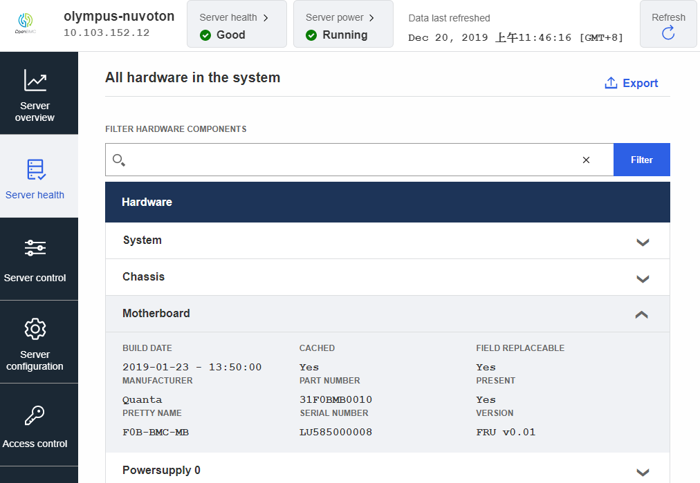
Field Replaceable Unit. The FRU Information is used to primarily to provide “inventory” information about the boards that the FRU Information Device is located on. In NPCM750, we connect EEPROM component as FRU Information Device to support this feature. Typically, this feature is used by the BMC to "monitor" host server health about H/W copmonents status.
Source URL
This is a patch for enabling FRU feature in phosphor-impi-fru on Nuvoton's NPCM750.
How to use
-
Modify DTS settings of EEPROM for FRU. For example about DTS nuvoton-npcm750-evb.dts:
i2c4: i2c@84000 {
    #address-cells = <1>;
    #size-cells = <0>;
    bus-frequency = <100000>;
    status = "okay";
    eeprom@54 {
        compatible = "atmel,24c64";
        reg = <0x54>;
    };
};
According DTS modification, you also need to remember modify your EEPROM file description content about SYSFS_PATH and FRUID. Below is example for our EEPROM file description motherboard:
SYSFS_PATH=/sys/bus/i2c/devices/3-0050/eeprom
FRUID=1
SYSFS_PATH is the path according your DTS setting and FRUID is arbitrary number but need to match Fruid in config.yaml file. Below is example for when Fruid set as 1:
1: #Fruid /system/chassis/motherboard: entityID: 7 entityInstance: 1 interfaces: xyz.openbmc_project.Inventory.Decorator.Asset: BuildDate: IPMIFruProperty: Mfg Date IPMIFruSection: Board PartNumber: IPMIFruProperty: Part Number IPMIFruSection: Board Manufacturer: IPMIFruProperty: Manufacturer IPMIFruSection: Board SerialNumber: IPMIFruProperty: Serial Number IPMIFruSection: Board xyz.openbmc_project.Inventory.Item: PrettyName: IPMIFruProperty: Name IPMIFruSection: Board xyz.openbmc_project.Inventory.Decorator.Revision: Version: IPMIFruProperty: FRU File ID IPMIFruSection: Board -
Server health
Select
Server health->Hardware statuson Web-UI will show FRU Board Info/Chassis Info/Product Info area.
Maintainer
- Jim Liu & Brian Ma
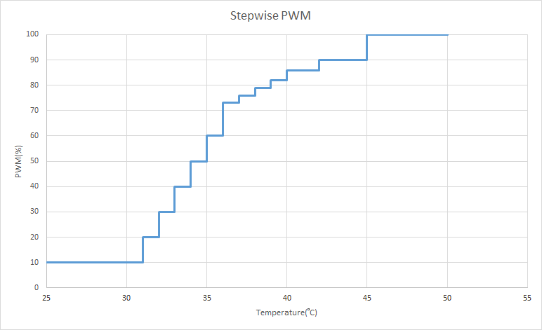
In NPCM750, we have two PWM modules and support eight PWM signals to control fans for dynamic adjustment according temperature variation.
Source URL
- https://github.com/openbmc/phosphor-pid-control
- https://github.com/openbmc/phosphor-hwmon
- https://github.com/Nuvoton-Israel/openbmc/tree/runbmc/meta-quanta/meta-olympus-nuvoton/recipes-phosphor/fans/phosphor-pid-control
How to use
In order to automatically apply accurate and responsive correction to a fan control function, we use the swampd to handle output PWM signal. For enable this daemon, basically we need configuring the swampd configuration file and deploy a system service for start this daemon as below steps.
NOTICE: In current solution, we only use stepwise mechanism to control fans. But the swampd also can controls fan with PID by tuning parameters according to customer platform.
-
The swampd(PID control daemon) is a Margin-based daemon running within the OpenBMC environment. It uses a well-defined configuration file to control the temperature of the tray components to keep them within operating conditions.
Here is a configuraion example shows how to using one PWM control more than one fans on system.
"sensors" : [
    {
        "name": "fan1",
        "type": "fan",
        "readPath": "/xyz/openbmc_project/sensors/fan_tach/fan1",
        "writePath": "/sys/devices/platform/ahb/ahb:apb/f0103000.pwm-fan-controller/hwmon/**/pwm1",
        "min": 0,
        "max": 255
    },
    {
        "name": "fan2",
        "type": "fan",
        "readPath": "/xyz/openbmc_project/sensors/fan_tach/fan2",
        "writePath": "/sys/devices/platform/ahb/ahb:apb/f0103000.pwm-fan-controller/hwmon/**/pwm1",
        "min": 0,
        "max": 255
    },
    {
        "name": "Core_0_CPU0",
        "type": "temp",
        "readPath": "/xyz/openbmc_project/sensors/temperature/Core_0_CPU0",
        "writePath": "",
        "min": 0,
        "max": 0,
        "timeout": 0
    },
],
"zones" : [
    {
        "id": 0,
        "minThermalOutput": 0.0,
        "failsafePercent": 100.0,
        "pids": [
            {
                "name": "fan1",
                "type": "fan",
                "inputs": ["fan1"],
                "setpoint": 40.0,
                "pid": {
                    "samplePeriod": 1.0,
                    "proportionalCoeff": 0.0,
                    "integralCoeff": 0.0,
                    "feedFwdOffsetCoeff": 0.0,
                    "feedFwdGainCoeff": 1.0,
                    "integralLimit_min": 0.0,
                    "integralLimit_max": 0.0,
                    "outLim_min": 3.0,
                    "outLim_max": 100.0,
                    "slewNeg": 0.0,
                    "slewPos": 0.0
                }
            },
            {
                "name": "Core_0_CPU0",
                "type": "stepwise",
                "inputs": ["Core_0_CPU0"],
                "setpoint": 30.0,
                "pid": {
                    "samplePeriod": 1.0,
                    "positiveHysteresis": 0.0,
                    "negativeHysteresis": 0.0,
                    "isCeiling": false,
                    "reading": {
                        "0": 25,
                        "1": 26,
                        "2": 27,
                        "3": 28,
                        "4": 29,
                        "5": 30,
                        "6": 31,
                        "7": 32,
                        "8": 33,
                        "9": 34,
                        ...
                    },
                    "output": {
                        "0": 10,
                        "1": 10,
                        "2": 10,
                        "3": 10,
                        "4": 10,
                        "5": 10,
                        "6": 20,
                        "7": 30,
                        "8": 40,
                        "9": 50,
                        ...
                    }
                },
            },
        ],
    },
]
The PID README provide more detail about the meaning for each parameter.
Roughly speaking, there are two main section in configuration file: sensor and zones. Sensors defined the all component which are involved PID like temperature sensors, or fans. Zones defined the mechanism how the swampd control each fans by setting parameters.
The most important in sensors section is the settings of
readPathandwritePath. Sensors like temperature sensor or margin sensor must only set readPath, and fill up empty string to writePath. Fans could set the D-Bus path to readPath, also set the pwm system path to writePath. More detail about readPath and writePath please refer README that mentioned above.There are four PID controller types user can use:
fan,temp,margin, andstepwisein zones. User can tune the PID parameters following the tuning README.In above example case, the fan PID controller has a lot of PID parameters. And we only use the stepwise controller to control whole zone, so the PID parameters in fan controller like
integralCoefforoutLim_maxwould not work. And the parameterinputsfor stepwise controller must be thermal sensor. Please note the parametersetpointis no meaning for typefanandstepwisecurrently, and cannot be left out.If user want to control whole zone by stepwise controller like example configuration, the key point is set reading and output. The
stepwisePID use the mapping of reading and output value instead of set RPM setpoint. The reading and output value should be a pair, and user can set 20 pairs in maximum, one more pairs at least. And thestepwisewill return output setpoint if temperature is larger than reading value. For example, assume here are pairs ofstepwisereading and output:{ "reading": {25, 26, 27}, "output": {10, 20, 30} }If the temperature reading is 25.5°C, the return value will be 10. And if the reading value is 26.5°C, the stepwise controller will set 20% RPM to fan(s).
-
OpenBMC will run swampd through phosphor-pid-control.service that controls the fans by pre-defined zones. Here is a example service.
[Service] Type=simple ExecStart=/usr/bin/swampd Restart=always RestartSec=5 StartLimitInterval=0 ExecStopPost=/usr/bin/fan-default-speed.sh- ExecStopPost that means an additional commands that are executed after the service is stopped.
Maintainer
- Jim Liu & Brian Ma
The Serial over LAN (SoL) via IPMI redirects the output of the server’s serial port to a command/terminal window on your workstation.
The user uses the ipmi tool like ipmiutil to interact with SOL via IPMI. Here the ipmiutil is used as an example.
The patch integrates phosphor-net-ipmid into Nuvoton's NPCM750 solution for OpenBMC.
Source URL
How to use
-
Download the ipmiutil according to the host OS in your workstation.
Here it's assumed that the host OS is Windows 10 and ipmiutil for Windows is downloaded and used accordingly.
-
Run SOL:
- Extract or install the ipmiutil package to a folder in your workstation in advance.
- Launch a command window and navigate to that folder.
- Input the following command in the command window.
ipmiutil sol -N 192.168.0.2 -U root -P 0penBmc -J 3 -V 4 -a - (Optional) Configure the
Propertiesof the command window to see the entire output of SOL.Screen Buffer Size Width: 200 Screen Buffer Size Height: 400 Window Size Width: 100 Window Size Height: 40
-
End SOL session:
- Press the "~" key (using the shift key + "`" key) and "." key at the same time in the command window.
- Input the following command in the command window.
ipmiutil sol -N 192.168.0.2 -U root -P 0penBmc -J 3 -V 4 -d
Maintainer
- Jim Liu & Brian Ma
JTAG master is implemented on BMC to facilitate debugging host CPU or programming CPLD device.
Source URL
The Intel® At-Scale Debug feature allows for using any host system to run the Debug tool stack while connecting to the target system across the network. The target system must have a BMC which has physical connectivity to the JTAG pins as a minimum requirement of functionality.How to use
Here uses the RunBMC Olympus server as example.
- switch JPC1 jumper on host to 2-3.
- configure GPIO40(BMC_XDP_JTAG_SEL_N) to connect BMC JTAG to Host CPU
echo 40 > /sys/class/gpio/export echo 0 > /sys/class/gpio/gpio40/value - configure BMC_TCK_MUX_SEL pin to CPU TCK
echo 22 > /sys/class/gpio/export echo 1 > /sys/class/gpio/gpio22/value - Run ASD daemon on BMC
asd -u -n eth1 --log-level=warning -p 5123 - Launch CScripts on debug host
Assume CScripts source folder = $CS, OpenIPC source folder = $OIPC Edit $OIPC/openipc/Config/SKX/SKX_ASD_RC-Pins.xml - Change ip address to BMC ip address Edit $OIPC/openipc/Config/OpenIpcConfig.xml - Change DefaultIpcConfig tag as <DefaultIpcConfig Name="SKX_ASD_RC-Pins"/> export IPC_PATH=$OIPC/openipc/Bin export LD_LIBRARY_PATH=$IPC_PATH Go to $CS/cscripts, execute "python startCscripts.py -a ipc" - Execute OpenIPC idcode operation in CScripts command prompt. It will show the TAP device's idcode.
>>> import ipccli
>>> ipc = ipccli.baseaccess()
>>> ipc.idcode(0)
BMC can load svf file to program CPLD via JTAG.
BUV can use J705 pin5 , pin7 , pin9 , pin13 to connect CPLD.
How to use
run loadsvf on Runbmc to program CPLD. Specify the svf file name with -s.
loadsvf -d /dev/jtag0 -s firmware.svf
Maintainer
- Jim Liu & Brian Ma
This is a secure flash update mechanism to update HOST/BMC firmware via LPC/PCI.
Source URL
- https://github.com/Nuvoton-Israel/phosphor-ipmi-flash
- https://github.com/Nuvoton-Israel/openbmc/blob/runbmc/meta-phosphor/nuvoton-layer/recipes-phosphor/ipmi/phosphor-ipmi-flash_%25.bbappend
The host-tool depends on ipmi-blob-tool and pciutils.
Check out the pciutils source.
Then run these commands in the source directory.
make SHARED=yes
make SHARED=yes install
make install-lib
Check out the ipmi-blob-tool source. Then run these commands in the source directory.
./bootstrap.sh
./configure
make
make install
Check out the phosphor-ipmi-flash source. Then run these commands in the source directory. If you choose "enable-nuvoton-p2a-vga", then the tool will support LPC and PCI-VGA. If you choose "enable-nuvoton-p2a-mbox", then the tool will support LPC and PCI-MailBox
./bootstrap.sh
./configure --disable-build-bmc-blob-handler --enable-nuvoton-p2a-vga
make
make install
How to use
-
If you want to do firmware update over LPC, then you need to check the memory address which BIOS allocates for LPC. You could use "ioport" tool and following commands to get the address.
sudo outb 0x4e 0x07 sudo outb 0x4f 0x0f # Host address a7-a0 sudo outb 0x4e 0xF4 sudo inb 0x4f # Host address a15-a8 sudo outb 0x4e 0xF5 sudo inb 0x4f # Host address a23-a16 sudo outb 0x4e 0xF6 sudo inb 0x4f # Host address a32-a24 sudo outb 0x4e 0xF7 sudo inb 0x4f # shm active? sudo outb 0x4e 0x30 sudo inb 0x4f -
Here is an example for upadting over LPC, and --length is fixed.
sudo ./burn_my_bmc --command update --interface ipmilpc --image image-bmc --sig image-bmc.sig --type image --address 0x817e0000 --length 0x1000 -
Here is an example for upadting over PCI(both VGA and MailBox)and --type is fixed
sudo ./burn_my_bmc --command update --interface ipmipci --image image-bmc --sig image-bmc.sig --type image
This is an OpenBMC IPMI Library (Handler) for In-Band Firmware Update.
How to use
-
You need to enable the way you want to transfer data from host to BMC
nuvoton-lpc enable-nuvoton-p2a-mbox enable-nuvoton-p2a-vga -
select the corresponding address for IPMI_FLASH_BMC_ADDRESS_nuvoton
0x7F400000
0xF0848000
0xc0008000
Maintainer
- Jim Liu & Brian Ma
reference with IPMI.md
reference with DCMI.md
| Type | Size | Note |
|---|---|---|
| image-uboot | 540 KB | u-boot 2019.01 + bootblock for NPCM750 only |
| image-kernel | 4.4 MB | linux 5.4.16 version |
| image-rofs | 23.0 MB | bottom layer of the overlayfs, read only |
| image-rwfs | 0 MB | middle layer of the overlayfs, rw files in this partition will be created at runtime, with a maximum capacity of 3 MB |
- 2020.07.27 First release ReadME.md
