Tuning
- Contents
- Post Build Checks
- Belt Tension
- AWD Y Stepper Motor Sync
- Heater Calibration
- Extruder Rotation Distance
- Z Offset
- Bed Tramming
- Bed Mesh
- Resonance Testing
- Printing
- Slicing
- Move the axis away from the endstops and have the QuickDraw probe docked on the printer
- Navigate to Mainsail>Machine tab and refresh the endstop status.
The result should be the following:

- Attach the QuickDraw probe on the toolhead and refresh the endstop status:

- Move the toolhead and the bed so they would trigger the endstops and check if their status changes to TRIGGERED (you will need to hit the refresh button).
- Perform the same checks by activating the microswitches from the toolhead and from the bottom of the Z rail.
To verify that the motors move in the correct direction perform the following checks:
- Move the bed, toolhead and Z axis to the middle
- Make sure all steppers are disabled, run M84
- Check that the axis move in the correct direction after running the corresponding command
Toolhead moves to the right
M84
FORCE_MOVE STEPPER=stepper_x DISTANCE=5 VELOCITY=10
Bed moves towards the front of the printer
M84
FORCE_MOVE STEPPER=stepper_y DISTANCE=5 VELOCITY=10
M84
FORCE_MOVE STEPPER=stepper_y1 DISTANCE=5 VELOCITY=10
Left side of the Z axis moves up
M84
FORCE_MOVE STEPPER=stepper_z DISTANCE=1 VELOCITY=5
Right side of the Z axis moves up
M84
FORCE_MOVE STEPPER=stepper_z1 DISTANCE=1 VELOCITY=5
Wrong direction
- To reverse the direction of a motor you have to flip the
dir_pin:from printer.cfg by either adding or removing a!character in front of the pin name. E.g: dir_pin: !PE10
Motors sides reversed
- If the motors don't match the intended side, then you have to swap their plugs from the mainboard or breakout board side. E.g. Z swapped with Z1
- The recommended belt tensions are the following:
X - 108hz (Carriage all the way to the left)
Y - 118hz (Carriage all the way to the back)
Z - 90hz (Pluck the rear belt segment)
- Move the carriage all the way to the back
- Loosen up the front motor pulley grub screws
- Insert the Y belt tool with the tensioning side towards the bed (check for markings on the tool) and under the carriage.
- Note: the bed doesn't have to be removed
- Insert the hex key into the tool channels until it reaches the tensioning screw and tighten/loosen both screws progressively.
- Adjust while verifying the belt frequency
- Finish by tightening the pulley grub screws or by running the stepper sync procedure.
- To measure the belt frequency you can use the Prusa Belt Tool on your phone. Ignore the recommendations shown there and just follow the frequency.
- Or you find a musical tuner app that displays frequency e.g Pano Tuner (iOS/Android)
➡️ To check the latest recommendations, or to calculate your own belt tension requirements you can use the following link:
LHS Belt Tension Calculator
Note: If you setup is non standard, then you have to measure the plucked belt length span and input it in the spreadsheet (You have to make a copy first)
In an AWD setup where two stepper motors are active on the same belt loop, a sync procedure is required to ensure a smooth operation.
Failing to do so this will results in a loss of torque and increased vibrations.
You can perform the following test to determine if the steppers are de-synced:
- With the steppers disabled, move the bed backwards. Pluck the belt listening to the tone.
- Run the "FORCE SET POS" macro, pluck the belt and listen if the tone changed.
- Keep plucking while disabling the steppers.
- If the frequency changes, that means the steppers are de-synced.
- If it doesn't, you can repeat the test with the bed in a slightly different position.
Note: you can use an app or some other method to get a reading of the belt frequency between disabled and enabled steppers, as described in the Belt Tension section.
- Whenever the belt tension has changed
- If you skipped steps
The Stepper Sync process has to be done after re-tensioning the belt, in case of setup changes, or in case of skipped steps during printing or speed tests.
New setups in which the belt tensioners or the mounts have not settled in their final positions might require repeating the procedure at smaller intervals.
Process:
Note: the following procedure is done only on the front stepper motor. The rear one doesn't require any adjustments.
- Make sure that both grub screws of the front pulley tighten into the round part of the shaft. Use a Sharpie on end of the stepper shaft to mark the D location
- Disable the steppers and move the bed towards the middle, ensuring that the pulley ends up in a location where you have access to the grub screws
- Loosen up the grub screws and run the "AWD SYNC" macro a couple of times.
- After running the macro for the last time, keep the stepper engaged and tighten back the grub screws
- Disable the steppers
You can follow the steps described in the beginning of the page to check if the sync procedure was successful.
Troubleshooting:
If your belt frequency changes between enabled and disabled steppers stages when your pulley is loose, that means that the pulley is stuck on the shaft.
In this case, while the steppers are enabled, nudge the pulley with the hex key inserted into the grub screw and try to match the frequency of the belt between the active and disabled steppers state.
Procedure
- Home the printer and move the toolhead to the center of the bed, and 20mm height on Z
G0 X127 Y127.00 Z20 F4000
- Set the Fan Speed to 30% (Aux Fan included)
- Wait until the heaters are at ambient temperature and then run the calibration command
- Remember to save at the end
- Set your calibration target to your regular printing temperature
Hotend:
PID_CALIBRATE heater=extruder target=230
Bed:
PID_CALIBRATE HEATER=heater_bed TARGET=60
- Uncomment the [include mpc_calibrate.cfg] line in printer.cfg during the calibration process and turn it back off at the end
- MPC doesn't require the calibration to be done at printing temperatures, and the values below have proved to perform well
- The 90C bed temperature is at the lower end of what MPC can use for calibration
- Leave the fan speed at 0, MPC will control it during the calibration process
Hotend:
MPC_CALIBRATE HEATER=extruder TARGET=200 FAN_BREAKPOINTS=7
Bed:
MPC_CALIBRATE HEATER=heater_bed TARGET=90 FAN_BREAKPOINTS=7
- Load PLA and set the nozzle to a high temperature such as 235C to overcome potential backpressure issues
- Have a length of unspooled filament Mark 120mm of filament from extruder entrance
- Extrude with the settings below and measure the distance of the filament left between the extruder entrance and the mark.
- If it's 20mm, your rotation distance is stop on.
- If not, use to following formula to adjust the [extruder] rotation_distance
RD = (120 - distance_left)/100 * previous_rotation_distance
- If not, use to following formula to adjust the [extruder] rotation_distance

❗ Note: Before setting up the Z-Offset, it is recommended to hot tighten your nozzle and nozzle extender by heating up your hotend above your maximum printing temperature (~290C) and tightening them at around 1.8Nm of torque (light-medium torque). When tightening the nozzle into the extender, make sure to hold the extender so that you won't screw both at the same time into the heater block.
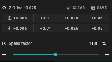
For setting up the Z-Offset I prefer to using the following workflow:
- Run the "PARKCENTER" macro to home and position the nozzle in the center of the bed
- Lower the toolhead to Z: 2mm using the main Toolhead controls
- Place a paper under the nozzle and lower Z further to 0. If it touches at 0, increase the Z-Offset using the controls depicted above.
- Start lowering the Z-Offset until you just feel the nozzle scraping the paper
- Click the Save button
This procedure assumes your Extruder rotation distance was previously calibrated.
- Start printing a single large flat layer
- Babystep the Z-Offset while printing to fine adjust your Z-Offset
- Remember to save your setting when reaching the desired result
Note: When printing with higher nozzle temperatures, reaching 300C, you will have remember to increase the Z-Offset to compensate for the nozzle thermal expansion.
While the Z Tilt procedure takes care of the X bed to gantry alignment (to a certain point), the bed requires to be trammed on the Y axis for optimal bed flatness. This will ensure alignment between the bed plate and the direction of motion.
This procedure will require adjusting the cart mounts position or shimming the bed screws with washers, paper, or other materials that not creep under heat. Just ensure that the outer diameter of the shim is small enough not to damage the PI heater.
Procedure
Note
Throughout this procedure we will be disregarding the left vs right side alignment, and focus only on the front vs back alignment for each side. The alignment between the left and right sides is done automatically by Z-Tilt procedure. Ignore the values of the extreme corners as well.
- Run a home and tilt process by using the "QD HOME TILT" macro
- Generate a bed mesh
If you encounter issues with Y deviances of 0.5mm or larger, those most probably stems from the alignment/twist of the rail cart mounts.
In the example below the Points 1 and 2 are almost perfect, while points 3, and 4 display an extreme twist (>1mm).
One of the rail cart mounts is twisted compare to the rest of the assembly.
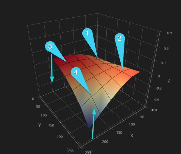
- Grab the bed with both arms (front and back) on the side that displays twist and force it to twist in the opposite direction.
- Generate a bed mesh again. If nothing change, you might have to loosen a bit the side screws of the mount to rail cart on that side.
- Repeat the procedure until you get the the front and back into alignment in an acceptable range.
- Tighten the cart mounts when done
An alternative quick and dirty method is by using the probe as a visual reference illustrated in the video below.
tram.mp4
If the bed twist comes back after some use, then it's most probably caused by the process of detaching printed parts off the bed by using extreme force. This can shift the cart mounts from their position and rotate the entire bed assembly.
Before (Twist caused by cart mounts)
 After
After
 Images by @abstractFlo
The following procedure is meant for bringing the deviation range under 0.2 or 0.1mm
- Run a home and tilt process by using the "QD HOME TILT" macro
- Generate a bed mesh

- Looking at the Y axis, take note of the Z values of the points marked above (hover the mouse cursor over the points to read the values).
- We want the Z values of the A1 and A2 points to match. The same with the B1 and B2 pair.
- In case they are different, for example: B1 Z:0.5, and B2 Z:-0.5, you need to shim and raise the B2 screw location by 1mm to get have both points in the same plane.
- After inserting the shims and tensioning the screws with the same torque, repeat the procedure above.
- A caliper will help you measure the shim thickness during this process.
Note: Sometimes the bed might end up over-constrained due to the order (and torque) the bed screws were tightened. You can compensate for this by tightening the screws progressively in sequence. Pushing or pulling on the bowed areas could also help a bit.
Make sure to evaluate the final result by running "QD HOME TILT" macro again and generating a new bed mesh.
If you experience a large amount of twist, please check the Extreme Twist in the Troubleshooting section below.
Warning
Do not try to tram the bed by removing the washers or spacers from the initial printer setup. You can risk damaging the PI bed heater if it comes in contact with the screws under the bed, resulting in a potential fire risk. It is always recommended to increase the bed to carriage spacing instead of trying to lower it.
Tip
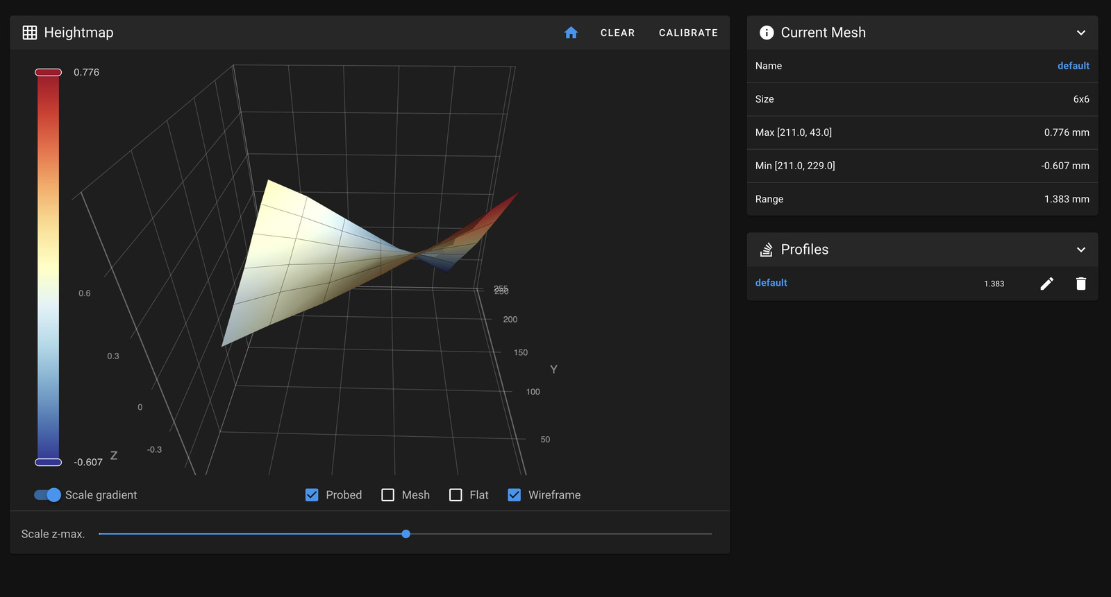
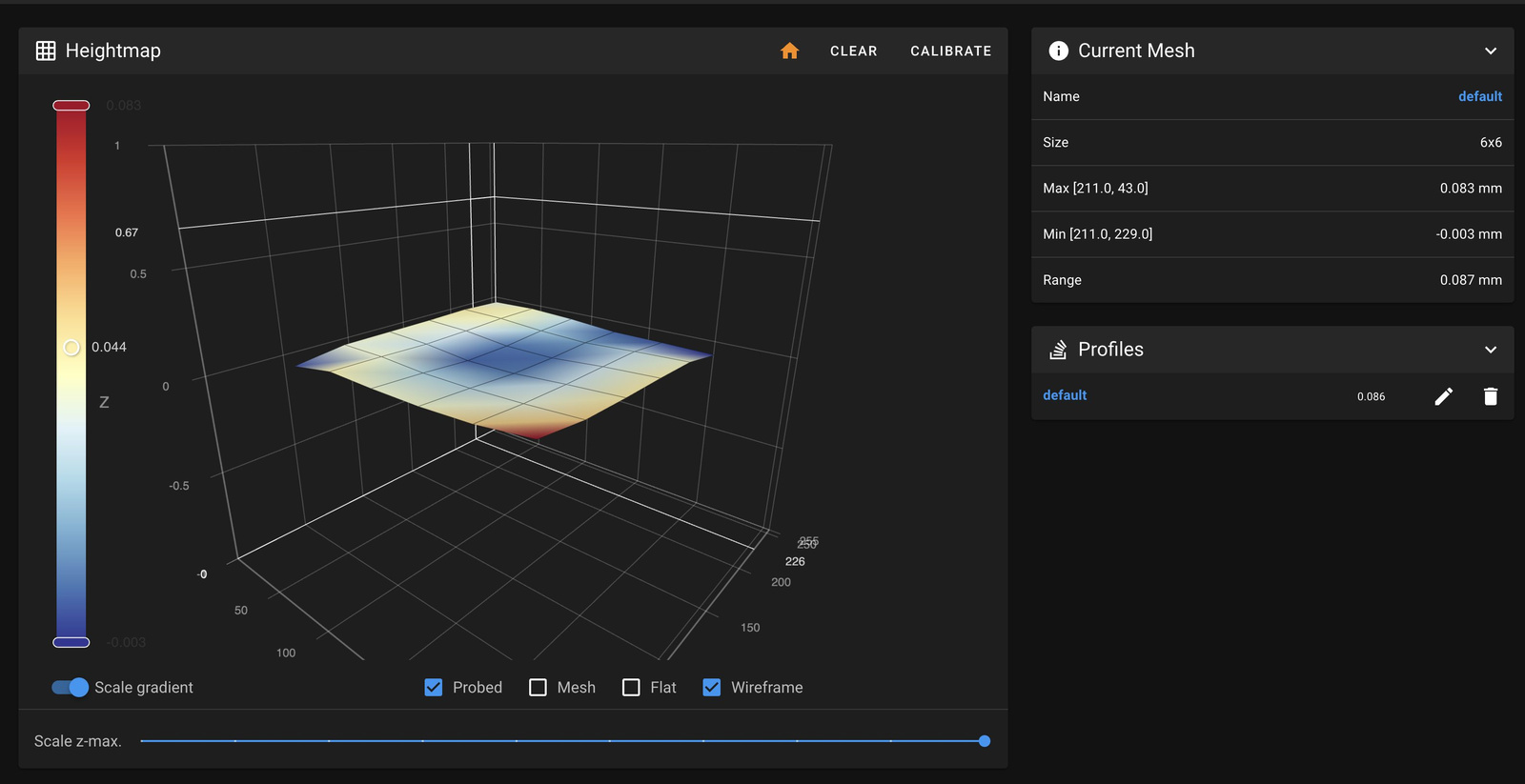
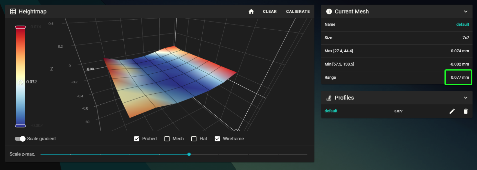
The final results can be deceiving based on the color visualization and Z-max scale.
Always observe the Range value. A range between 0.1 and 0.2 will give good results.
Note that the bed mesh is set to sample the very edge of the bed. "Spike" measurements can occur in these areas, and is better to disconsider them when evaluating the flatness.
Putting some effort into this process can give good results. The CF plate assembly can be very forgiving to tramming, and maintains the same flatness during heat cycles due to the very low thermal expansion of the CFRP characteristics.
❗ Do not get carried away with this process right after setting up the printer. Parts need to settle down and you might have to do other adjustments that might require removing the bed plate. Aim for something satisfactory and come back and redo this process later on.
Things can become frustrating trying to reach perfection. Take a break, do some prints, and come back to at some later date.
- If the bed tilt is not satisfactory on the X axis (left to right), the you might need to adjust the [z_tilt] point locations in the quickdrawprobe.cfg file.
It is possible that the points sampled for Z Tilt are not ideal, and are in an area that is not flat.
In the latest Stinger configuration the sample points were moved more towards the center to avoid bowed edges which can give wrong tilt results. - Another issue can be caused by the probe body touching the bed. Observe the probe during the X tilt calibration process.
Calibration
- Home the printer and move the toolhead manually using the dashboard controls to the bed origin (left front).
- Compare the values to the reference origin (X18, Y38) used here
- If they differ, then add those offsets to the min/max X,Y values below in the
[bed_mesh]section of quickdrawprobe.cfg - Run a BED_MESH_CALIBRATE to test your configuration while holding your hand on the
EMERGENCY STOP - Update your slices bed mesh Origin setting if needed as described in the Macros - Bed Origin Guide

❗ For safety reasons it is recommended to patch the screw holes with some squares of kapton tape.
If the probe reaches one of the holes it might not to trigger and will cause a toolhead crash into the bed.

Note
To streamline your Resonance Testing process, it's recommended to utilize ResHelper.
The following guide was updated to make use of the new sweeping vibrations resonance test from Klipper. This produces more consistent readings with less tuning required.
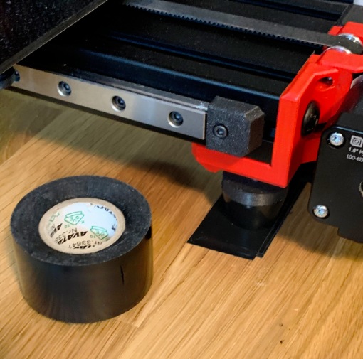
- The X axis is tested with the ADXL probe mounted on the toolhead while the Y axis uses the provided bed mounts (part of Other Parts.3mf).
- The ADXL Y axis bed mount is secured with double sided mounting tape which should be very strong and thin <= 0.1mm.
- When testing the Y axis, the ADXL cable should be taped on the bed as well (using regular tape)

-
When setting up Resonance Testing, the primary objective is to gather accurate and repeatable data. One crucial parameter to tune is the "accel_per_hz" which determines the intensity of vibrations during testing. This adjustment helps elevate the resonating peak above the noise floor level, revealing the system's true resonating frequency. Typically, stiffer or heavier systems require higher excitation to generate a peak resonant frequency.
The initial values in the LH Stinger configuration (adxl.cfg) serve as a good starting point, calibrated based on empirical testing considering the weight and stiffness of each axis.
The most optimal accel_per_hz values found for the sweeping test are the following:
X Axis - accel_per_hz: 60
Y Axis - accel_per_hz: 90
❗ Aim for graphs displaying peaks above 1e5 Power Spectral Density (PSD) scale. If the result is lower, the graph might display totally false data, so always check for this!
 |
 |
|---|
After establishing a baseline measurement workflow, proceed with tuning or debugging your system. If the results are inconclusive, please use the included configuration defaults in the mean time.
The list below contains what I found to be the most important points to address when debugging issues regarding multiple peaks appearing on the Y axis.
The X axis is way more forgiving and doesn't require much tuning.
-
Stepper Synchronization and Belt Tension: Verify that the steppers are synced and the belt tension is set correctly by using the guides above. On a new system this might take a bit to stabilize, and usually the longer the printer sits without being tweaked, the better it will measure in time as things settle down. Desynced stepper motors will cause the system to oscillate and generate multiple phasing peaks. This peak movement (phasing) can be observed during consecutive resonance tests.
-
Y Feet Leveling and Weight Distribution: Ensure that the feet on the Y axis are perfectly level and evenly distribute the weight of the printer. If the rest of the frame (especially the middle frame member under the Y extrusion) carry some of the weight of the Y assembly, it can cause the entire system to behave like a seesaw, leading to front and back rocking motion.
This is the reasoning behind the softer pads under the Z pillars, as it is preferred to be able to slightly rock the printer side to side when applying pressure. This confirms that the Y axis carries it own weight in addition to some of the rest of the frame. You can think of it as setting it up so that the bottom X extrusion slightly hangs from the bottom of the Y axis.
-
Bed Cable and Strain Relief: The bed cable and strain relief mechanism can sometimes cause secondary peaks. To check for this issue, hold the bed cable at an angle during resonance testing by hand, or disconnect the strain relief and allow the cable to hang freely. Please follow the recommended way of routing the bed cable downwards the Z pillar as is depicted in the CAD file.
-
Run the steppers in steppersfast.cfg configuration mode. This ensures that torque is not a bottleneck when it comes to overcoming issues such as binding.
- Note: The final input shaping values should be measured and set according to the settings used, respectively, steppers.cfg and steppersfast.cfg. The input shaping parameters are set inside those files.
- Increasing stepper motor current (torque) also results in an increase of peak resonant frequency.
- If you encounter overheating warnings you can slightly reduce the stepper driver current and keep the drivers disabled for cool down between tests.
- You can use the "FORCE SET POS" macro if you need to reset the printer and you want to test again from the same location without homing. This macro force sets the axis homed to the position from the adxl configuration. Just remember to disable steppers afterwards.
-
If you have issues triggering resonances in the 1e5 scale range even after increasing accel_per_hz (120+), try increasing the tension of the Y belt to 120HZ and re-sync steppers.
-
If further debugging is needed, then you can run the VIBRATION TEST macro at the problematic peak frequencies and start holding parts around the printer to find the sources of stray resonances. Please see the [resonance_holder] section in printer.cfg.
-
Change one thing at a time and A/B test against previous measurements done under identical conditions. Make sure to evaluate the results correctly since it's easy to be deceived by following the wrong parameters.
-
Once the Y Axis feet are level, you can experiment by placing one or more strips of PVC electrical tape under the Y feet (usually front) for shimming and fine tuning the weight distribution between front and back, and increasing the weight load on the Y assembly vs the rest of the frame as recommended in the tips above. A positive side effect of this, is that the rubber feet will "fuse" with the PVC tape in time, and will create a strong bond between the Y assembly and the surface below.
-
After determining the final values, if the suggested shaper for a specific axis is ZV shaper, it is generally advisable to opt for MZV and its recommended frequency instead. While ZV is highly efficient, its operational range is relatively narrow, which may not provide optimal reliability under typical printing conditions.
For detailed discussions and assistance, join the LH Stinger Discord featuring dedicated channels for Resonance Testing and Input Shaping issues.
At the time of writing, the LH Stinger prototype has undergone over 1100 resonance tests.
The following calibrations stay valid as long as the extruder/hotend/nozzle setup remains the same.
Important: Run the calibration tests with your regular profile at your regular printings speeds whenever possible!
Per filament:

Per filament type:

-
Max volumetric speed (Set your cooling to 100% and SCV to 60+)
-
Temperatures (Note: If you print a temperature tower, make sure you don't hit minimum layer time)
-
Cooling Parameters
When inspecting prints for Layer Stacking artifacts, before questioning your Z-axis, make sure to open the slicer and review the Speed, Flow, and most importantly, the Layer Time (log) in the g-code preview. In most cases, you'll be able to trace the source of these artifacts there.
These artifacts often result from irregular cooling of the previous layer, causing variations in the solidity of the plastic. When a new perimeter is squished onto that, the extrusion profile changes depending on the stiffness of the base it's laid upon.
This issue is more common in cooling-limited scenarios or layers with extreme variations in layer times.
Some infill profiles, such as "Cross Hatch," are also known to cause irregular layer times due to their changing profile every n layers.

On the LH Stinger, Z-axis mechanical issues will manifest as regular artifacts every 40 or 10mm intervals starting from an arbitrary height.
In that case inspect your Z drive pulleys and the tightness of the 188mm closed belt loop.