

By Yothinburana School Robot Club

Qualification Round (Time 37 sec) https://youtu.be/zxlOy2REIk4
Final Round (Time 45 sec) https://youtu.be/RNagUxmCIuk
- Design process
- Program explaination

Designing a robot is not easy. We will need to plan ahead about what you will use in the robot.
For WRO Future Engineer, it is mandatory that the robot uses one driving motor and one steering actuator of any type, and it is highly reccommended that our robot also have a camera. 📸
- Driving Motor ( Power Functions L-Motor )

A simple and fast motor made by LEGO. There are many alternatives when it comes to motors for a robot, but we chose this motor because of the ease of connecting this motor to the frame of our robot. We need to make sure that our robot does not break apart while running.
- Ultrasonic Sensor ( SEN0307 ) to measure the distance between the robot and the walls

An incredible sensor that comes with built-in temperature compensation, which can greatly reduce measurement error caused by over high/low temperature. It adopts analog voltage output, and provides accurate distance measurement within 2-500cm with 1cm resolution and ±1% accuracy.
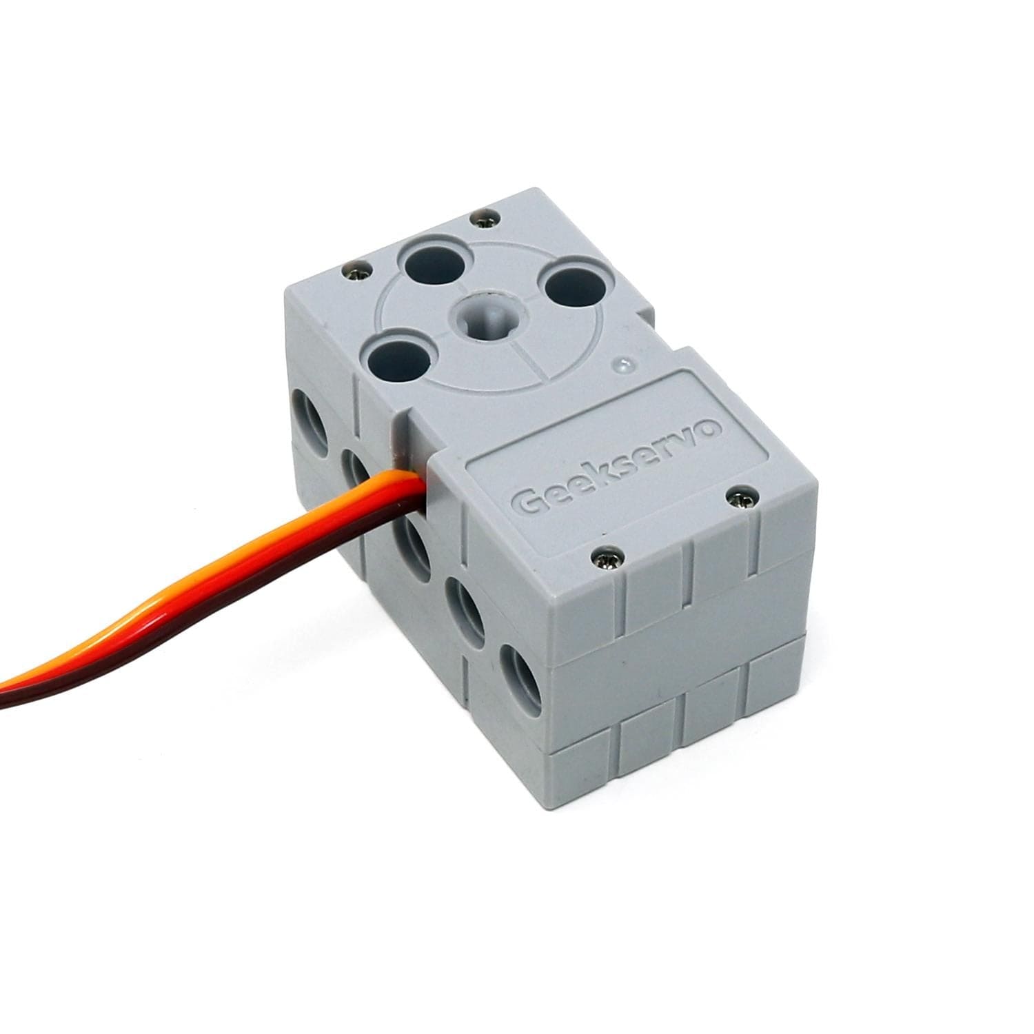
- Servo ( GEEKSERVO-270 ) one for steering our robot and another for rotating the ultrasonic sensor
- Color Sensor - We use ZX-03 to detext the color of the field.

- Compass or Gyro - We use GY-25 compass to determine the direction of our robot.

- Camera - We use Pixy 2.1 for our robot because of its functionality along with the existing pre-made library by the developers

- Microcontroller Board - Arduino UNO, the brain for our robot

- Shield L298P Motor Driver with GPIO, enables arduino UNO to drive motors
-800x800.jpg)
Wire connections for our robot
//  Motor B
int const ENB = 11;
int const INB = 13;

//  Servos
int const STEER_SRV = 9;
int const ULTRA_SRV = 8;

//  Ultrasonic Sensor
int const ULTRA_PIN = 2;

//  Light Sensors
int const RED_SEN = 0;
int const BLUE_SEN = 1;

//  Button
int const BUTTON = 3;

//  Pixy Camera
int const PIXY_SDA = 4
int const PIXY_SCL = 5

//  Gryo
// Connect to TX RX
- Arduino IDE 2.1.1 - For Programming your Arduino UNO
- Pixymon V2 - For displaying and configuring your Pixy
To be able to communicate with the sensors, many libraries need to be downloaded and included in this project. The libraries that will need to be downloaded will depend on what sensors you use. Most of these library are very crutial for completing the Qualification rounds and Final rounds.
All the libraries we use can be found using the Library Manager in Arduino IDE. except for the Pixy library which you need to download from this website.
#include  "Mapf.h"

#include  <Servo.h>

#include  <PID_v2.h>

#include  <Pixy2I2C.h>
Finally we got to the interesting part ✨ Please, download our Arduino program, and use it as a reference, so you can better understand our explainations.
For the setup(), we have to include some libraries and initialize the sensors in order for the robot to work as intended.
#include  "Mapf.h"
#include  <Servo.h>
#include  <PID_v2.h>
#include  <Pixy2I2C.h>

Pixy2I2C pixy;
PID_v2 compassPID(0.75, 0.001, 0.035, PID::Direct);

void  setup() {

	compassPID.Start(0, 0, 0);
	compassPID.SetOutputLimits(-180, 180);
	compassPID.SetSampleTime(10);

	// pinMode(BUZZER, OUTPUT);
	pinMode(ENB, OUTPUT);
	pinMode(INB, OUTPUT);
	pinMode(STEER_SRV, OUTPUT);
	pinMode(ULTRA_SRV, OUTPUT);
	pinMode(ULTRA_PIN, INPUT);
	pinMode(RED_SEN, INPUT);
	pinMode(BLUE_SEN, INPUT);
	pinMode(BUTTON, INPUT);

	Serial.begin(115200);
	pixy.init();
	while (!Serial);

	servo1.attach(STEER_SRV, 500, 2500);
	servo2.attach(ULTRA_SRV, 500, 2500);
	steering_servo(0);
	ultra_servo(0, 'L');

	// check_leds();
	while (analogRead(BUTTON) > 500);
	zeroYaw();
	while (analogRead(BUTTON) <= 500);
}The program can be simplified to the following parts:
Variables that affect the steering incudes:
- The input degree [ The direction we want to robot to steer to ]
- The direction of the robot measured by the compass sensor [ The direction that the robot is currently facing ]
- The distance between the wall and the robot measured by the ultrasonic sensor [ Preventing the robot from ramming into the wall ]
void  loop() {

	long countdown_stop = millis();
	while (analogRead(BUTTON) > 500) {
	getIMU();
	line_detection();
	ultra_servo(pvYaw, TURN);
	int wall_distance = getDistance();
	motor_and_steer(-1 * compassPID.Run(pvYaw + ((wall_distance - 25) * 1) * ((float(TURN == 'R') - 0.5) * 2)));

	if (millis() - countdown_stop > 1200) {
		// Stops everything
		motor(0);
		while (true);
	}

	if (lines_detect_num < 12) {
		countdown_stop = millis();
		}
	}

	while (analogRead(BUTTON) <= 500);
	...
}Variables that affect the speed of the motor includes:
- The direction of the robot measured by the compass sensor [ If the robot is facing in the wrong way, reduce the speed (give it more time to think) ]
void  motor_and_steer(int degree) {
	degree = max(min(degree, 45), -45);
	steering_servo(degree);
	motor(map(abs(degree), 0, 45, 80, 40));
}
🔴 Turn the robot when a line is detected - There are 2 lines on each corner of the field. This program detects those lines and adjusts the robot heading.
Variables that affect the turning of the robot includes:
- The Reflected light values measured by the Light Sensors
void  line_detection() {
	int blue_value = analogRead(BLUE_SEN);
	if (TURN == 'U') {
		int red_value = analogRead(RED_SEN);
		if (blue_value < 600 || red_value < 600) {
			int lowest_red_sen = red_value;
			long timer_line = millis();
			while (millis() - timer_line < 100) {
				int red_value = analogRead(RED_SEN);
				if (red_value < lowest_red_sen) {
					lowest_red_sen = red_value;
				}
			}
			if (lowest_red_sen > 600) {
				// Red
				TURN = 'L';
				compass_offset += 90;
			} else {
				// Blue
				TURN = 'R';
				compass_offset -= 90;
			}
			lines_detect_num++;
			halt_detect_line_timer = millis();
		}
	} else {
	if (millis() - halt_detect_line_timer > 1000) {
		if (blue_value < 600) {
			if (TURN == 'R') {
			compass_offset -= 90;
			} else {
			compass_offset += 90;
			}
			halt_detect_line_timer = millis();
			lines_detect_num++;
			}
		}
	}
}
This program ends after turning at the corners of the field 12 times (3 rounds).
The program can be simplified to the following parts:
Variables that affect the steering incudes:
- The color and position of the color blocks detected by the camera [ Adjusts the heading of the robot to avoid hitting the detected objects on the field ]
- The input degree [ The direction we want to robot to steer to ]
- The direction of the robot measured by the compass sensor [ The direction that the robot is currently facing ]
- The distance between the wall and the robot measured by the ultrasonic sensor [ Preventing the robot from ramming into the wall ]
void  loop() {
	long countdown_stop = millis();
	while (analogRead(BUTTON) > 500) {
		getIMU();
		ultra_servo(pvYaw, Blocks_TURN);
		line_detection();
		float distance_wall = getDistance();
		float steering_degree = -1 * compassPID.Run(pvYaw + ((distance_wall - 27)) * ((float(Blocks_TURN == 'R') - 0.5) * 2));
		if (millis() - pixy_timer > 50) {
			avoidance_degree = calculate_avoidance();
			pixy_timer = millis();
		}
		int final_degree = map(max(found_block, found_block_factor), 1, 0, mapf(min(max(distance_wall, 5), 40), 5, 40, steering_degree, avoidance_degree), steering_degree);
		if (millis() - halt_detect_line_timer > 2000 && lines_detect_num >= 12) {
			// Stops everything
			motor(0);
			while (true);
		}
	}

	motor_and_steer(final_degree);
	}
	motor(0);
	while (analogRead(BUTTON) <= 500);
	...
}
For calculating the degree in which the robot needs to turn to avoid the color blocks, the program can be simplified as follows:
- Calculating the distace between the camera and the object using the following formula:
distance = size_obj * focal_length / size_obj_on_sensor
After calculating the distace, we need to calculate the position of the block using **Trigonometry**.
pixy.ccc.getBlocks();
...

float(atan2(1000 * 2 / pixy.ccc.blocks[nearest_index].m_height * tan(float(map(pixy.ccc.blocks[nearest_index].m_x, 0, 316, -30, 30) + Wrap(bearingPID - initial_deg, -180, 179)) / 180 * PI) - 20, 1000 * 2 / pixy.ccc.blocks[nearest_index].m_height - 10)) * 180 / PI
But what is atan2? It is the 2-argument arctangent. By definition, degree (radians) = atan2(y,x)
Find out more about atan2: atan2 - Wikipedia
As shown in the program above, we can calculate the steering degree using the atan2 function. Setting the y position by measuring the position of the color blocks in 3D space using the Pixy camera then minus or plus 20 (cm) to offset the y position, so that the robot won't hit the detected block. The same goes for the x position, and then we get the final steering degree! ✨
🛣️ Changing the Speed of the Driving Motor - Communicate with L298n to drive the motor at a specified speed with a specified acceleration.
Variables that affect the speed of the motor includes:
- The direction of the robot measured by the compass sensor [ If the robot is facing in the wrong way, reduce the speed ]
Uses the same code previously mentioned
🔴 Turn the robot when a line is detected - There are 2 lines on each corner of the field. This program detects those lines and adjusts the robot heading.
Variables that affect the turning of the robot includes:
- The number of color blocks detected by the camera [ To ensure that the robot turns at the corner of the field AFTER successfully avoiding the objects on the field ]
- The Reflected light values measured by the Light Sensors
Uses mostly the same code previously mentioned
This program ends after turning at the corners of the field 12 times (3 rounds).
For further questions please email [email protected]