Assembly instructions
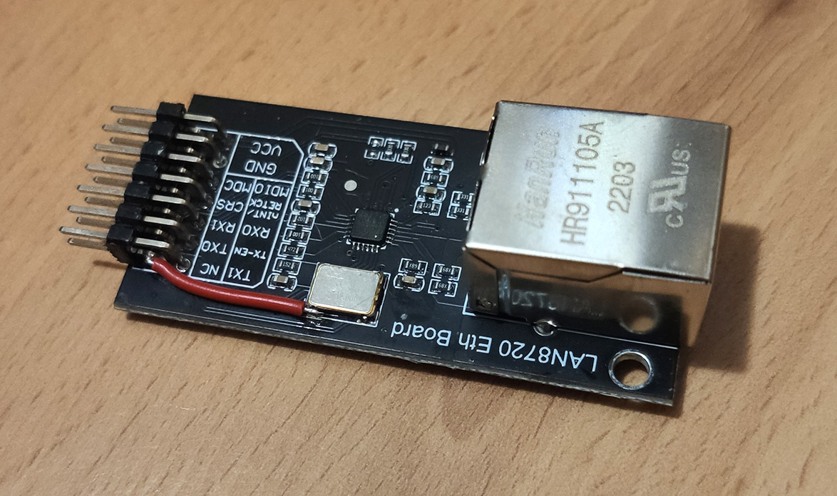
In order to properly boot the ESP32 you need to "fix" the breakout board - add a wire between spare pin on the header and 50MHz oscillator EN pin.
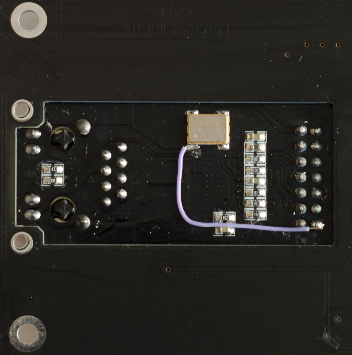
Warning: There is a version of the breakout board with the top-side oscillator that does not fit into the intended footprint. Make sure the version you are buying has the "LAN8720 Eth Board" marking above the RJ45 socket. The compatible version dimensions are 27x56(mm)
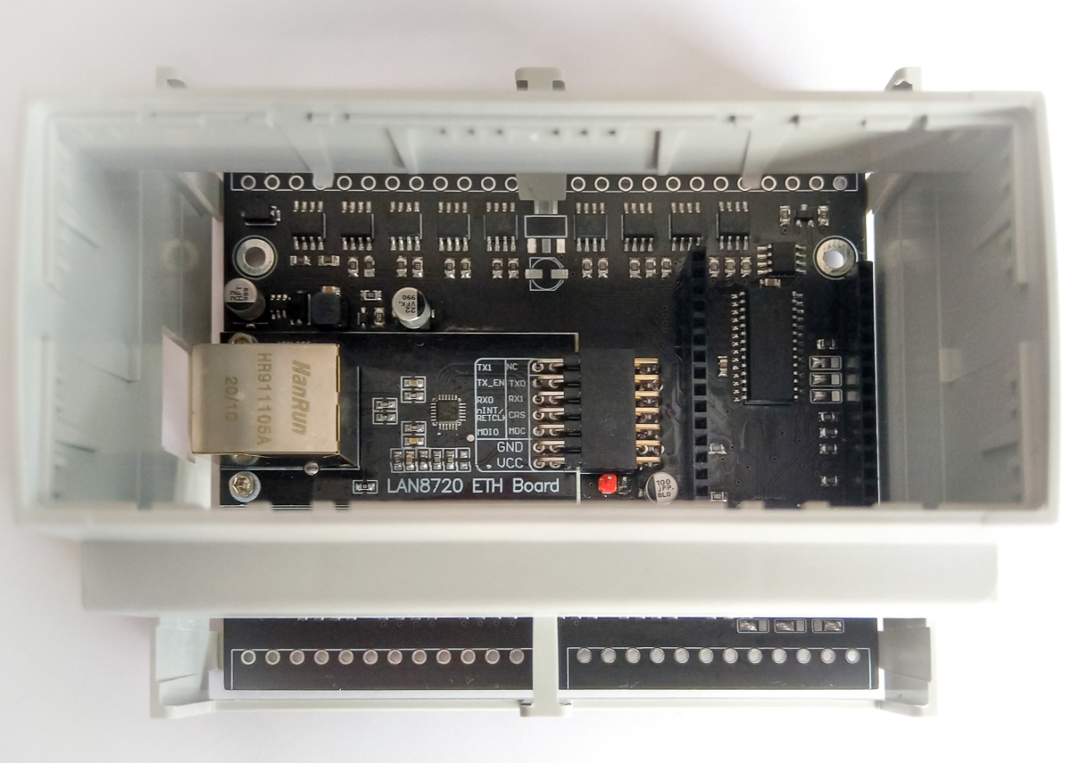
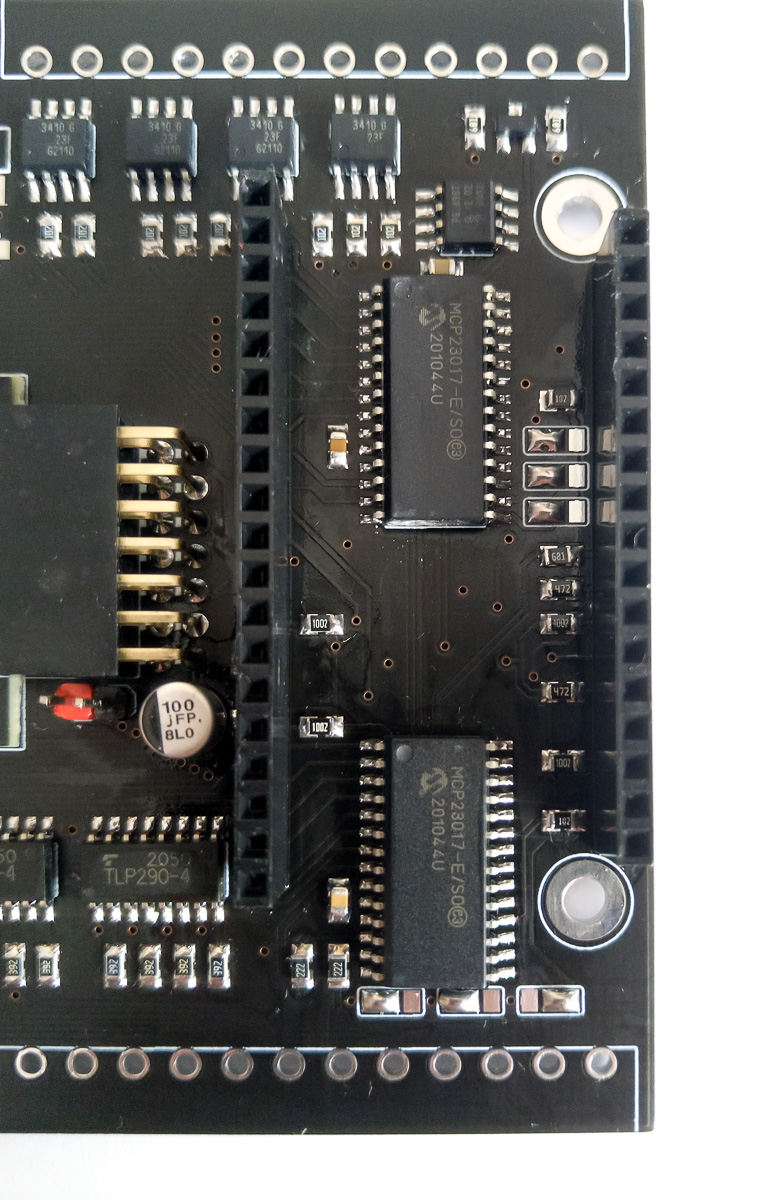
Everything except terminals!, component layout will help you out
- first program your ESP or flash empty sketch via USB not plugged to the main board
- now it's time to test the whole board
- test again, if you skip this step and you follow on, and the error appears later, you will have to break the plastic case in order to fix it
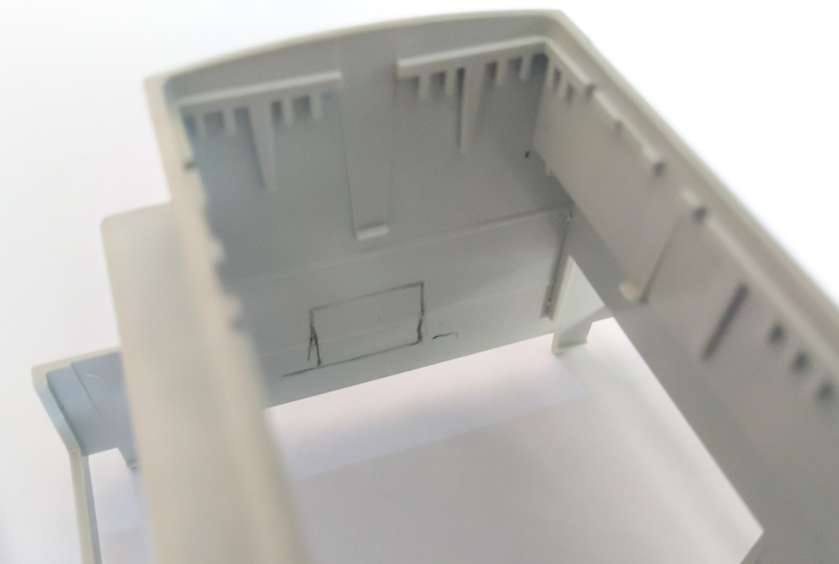
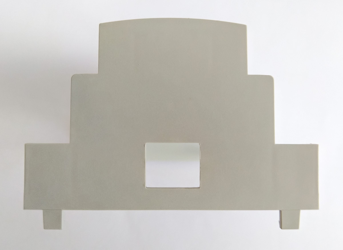
Outline the ethernet socket and drill/file the hole
Substract the height of the terminal by ~8mm. You can also buy version without sides (ZD3TCS ABS V0) bu you will ended up with the space above terminals
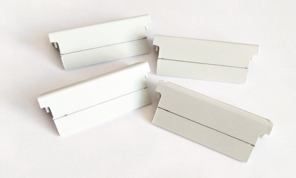
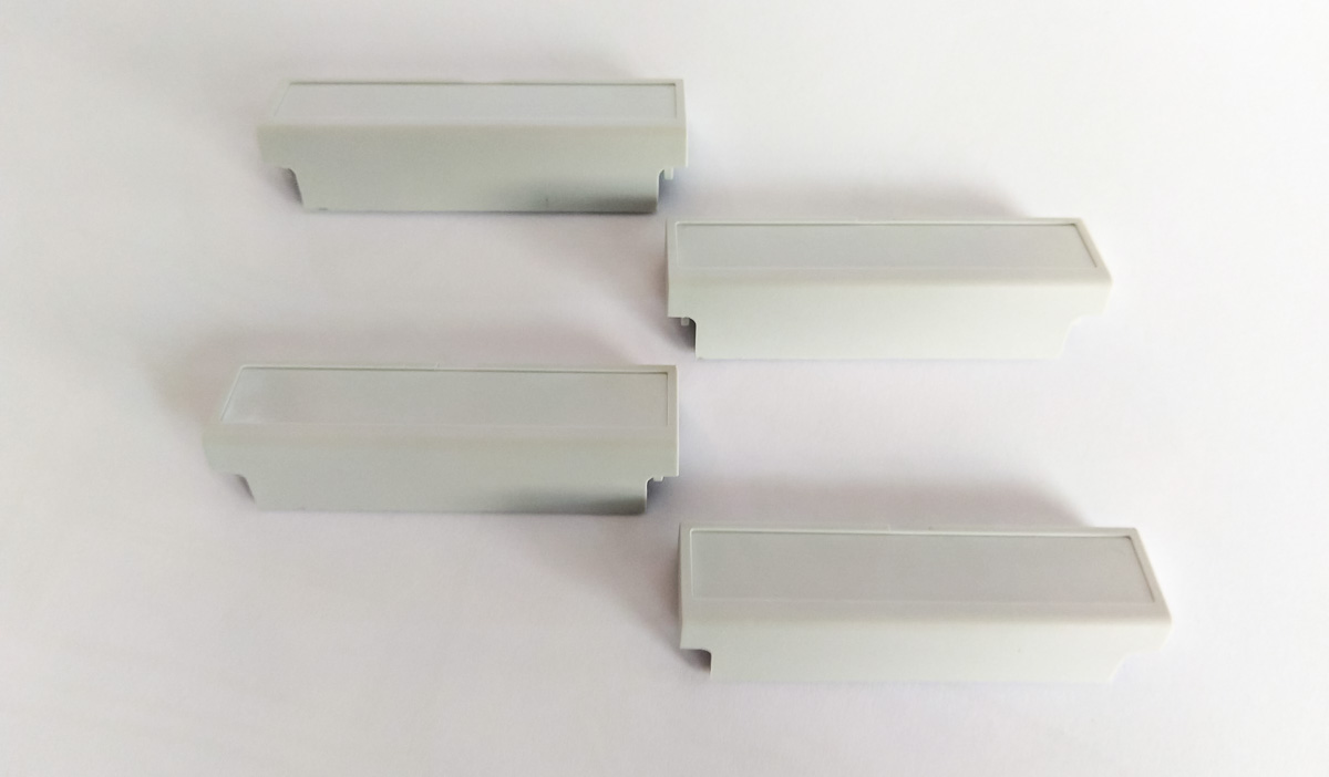
You will find that fitting the terminals into the plastic case is hard, adjust this area a little
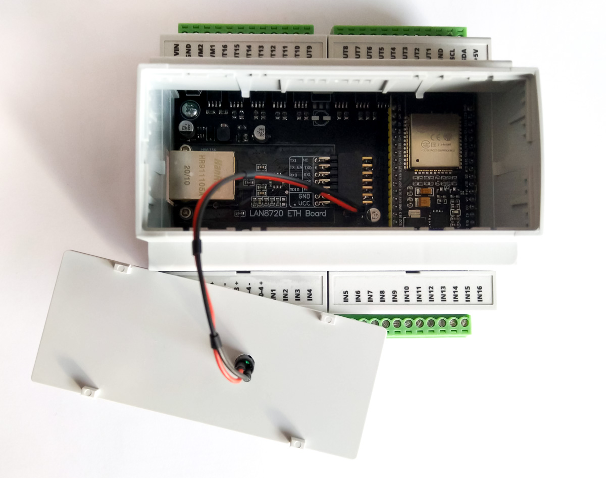
But first insert the PCB to the top part of the case, make sure ESP is unplugged
- close the case with bottom part and screw down the PCB.
- plug in the ESP (tricky part, but it's possible)
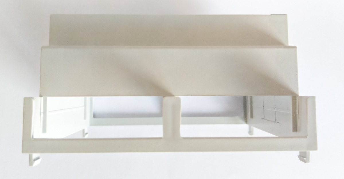
- drill 6mm (depends on the bezel clip holder) hole
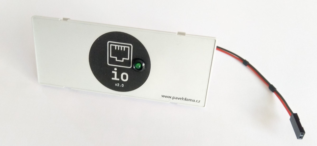
- solder wires to the LED
- crimp 2P header socket
This documentation is licensed under a Creative Commons Attribution-ShareAlike 4.0 International License.
