Copyright (C)2019-2022 VadRov / www.youtube.com/@VadRov / www.dzen.ru/vadrov
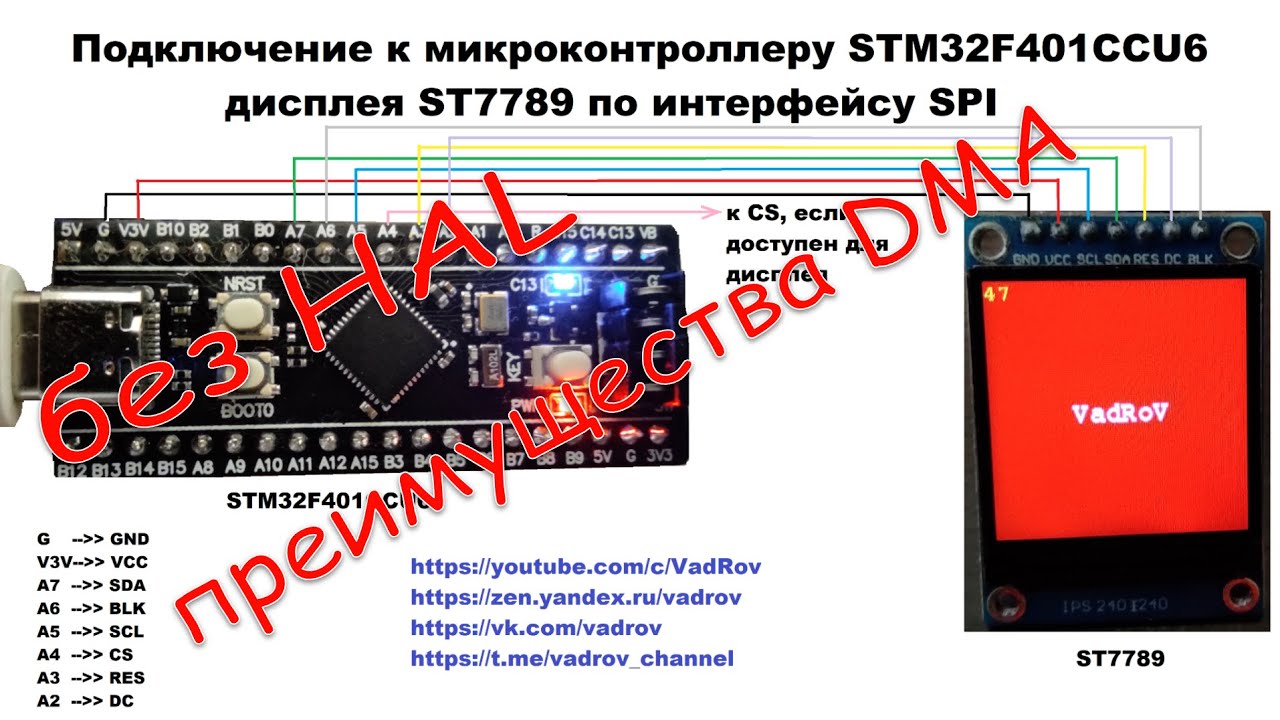
Control of a display (displays) connected with an SPI interface to a microcontroller of the STM32F4 family with DMA support, smooth change of backlight brightness via PWM. Displays with and without CS output are supported. Memory allocation control mechanism can be selected: static or dynamic (see display.h file).
The library (Display folder) contains low-level drivers for displays with ST7789 and ILI9341 controllers. To connect a display via SPI with another controller, you need to write your own low-level driver with initialization strings, etc., following the example of these drivers, referring to the specification of the corresponding display controller.
Graphic primitives (point, line, rectangle, etc.), text output, and data block (image) output to a specified area of the screen are available. Connection of user fonts is available (there are 3 of them in the library).
As an example, the project code created in the STM32CudeIDE environment shows the connection of displays with ST7789 and ILI9341 controllers to the STM32F401CCU6 microcontroller via SPI with DMA. The advantage of using DMA is demonstrated.
How to use the library and set up a project in the STM32CudeIDE environment is described in detail in the video:
- DMA settings are not in Circular mode, as in the video, but in Normal mode.
- Creating a handler for a new display is done by the LCD_DisplayAdd function, which creates and adds a display to the list of displays.
This list is declared in the library by the global variable LCD. After the first call to this function, you must reassign this (LCD) variable.
- For the option with dynamic memory allocation:
LCD = LCD_DisplayAdd (LCD, параметры дисплея...);- For the static memory allocation option:
LCD_Handler lcd1;
LCD = LCD_DisplayAdd (LCD, &lcd1, display parameters...);
You can get the handler address of the first display created for both options like this (although, for option 2, the handler address is obviously missing: &lcd1):
LCD_Handler *lcd = LCD;Thus, lcd will point to the address of the created display handler, which is also the first display in the list of LCD displays. If you need to connect another display and create a handler for it, then after performing the above steps, you should do the following:
- For the option with dynamic memory allocation:
LCD_Handler *lcd2 = LCD_DisplayAdd (LCD, second display parameters...);- For the option with static memory allocation:
LCD_Handler lcd_2, *lcd2;
lcd2 = LCD_DisplayAdd (LCD, &lcd_2, second display parameters...);
Thus, we get a pointer to the second display handler lcd2. Moreover, for the second option (static memory allocation), when accessing the display handler, the entry &lcd_2 is equivalent to the entry lcd2. Also, the pointer to the second display can be obtained like this:
LCD_Handler *lcd2_ptr = LCD->next;The demo project (see main.c) shows display initialization options using dynamic and static memory allocation. The memory allocation mechanism is determined by the LCD_DYNAMIC_MEM parameter in the display.h driver header file.
Two variants of LCD_DisplayAdd function prototypes
- For dynamic memory allocation:
LCD_Handler* LCD_DisplayAdd(	LCD_Handler *lcds, //List of displays (defined globally as LCD)
				uint16_t resolution1, //First of two physical dimensions of the display matrix in pixels
				uint16_t resolution2, //Second of two physical dimensions of the display matrix in pixels
						      //Dimensions can be specified in any order
				uint16_t width_controller,   //Maximum supported physical horizontal resolution of the display matrix by the display controller, pixels (designated as H in the specifications)
				uint16_t height_controller, //Maximum supported physical vertical resolution of the display matrix by the display controller, pixels (designated as V in the specifications)
				//Parameters w_offs and h_offs are used for non-standard and "curved" displays in which the origin of the physical display matrix
				//and the fields of the display controller do not match, i.e. they are shifted. They are determined based on a specific sample on hand and set the
				//"image centering" on the display. "Misalignment" manifests itself as a vertical or/and horizontal displacement of the image on the display.
				//It is typical for displays whose resolution is less than the resolution of the display controller used.
				int16_t w_offs, //Horizontal offset of the display matrix in the display controller field
				int16_t h_offs, //Vertical offset of the display matrix in the display controller field
				LCD_PageOrientation orientation, //Orientation: portrait or landscape, normal or mirror
				DisplayInitCallback init, //Display initialization function
				DisplaySetWindowCallback set_win, //Display output window definition function
				DisplaySleepInCallback sleep_in, //Display sleep mode enable function
				DisplaySleepOutCallback sleep_out,//Display sleep mode exit function
				void *connection_data, //Display controller connection data to the microcontroller
				LCD_DATA_BUS data_bus, //SPI data frame width (8 or 16 bits)
LCD_BackLight_data bkl_data); //Data for display backlight control- For static memory allocation: Parameters are similar, except for one additional lcd.
LCD_Handler* LCD_DisplayAdd(	LCD_Handler *lcds,
				LCD_Handler *lcd, //Pointer to user-defined display handler
				uint16_t resolution1,
				uint16_t resolution2,
				uint16_t width_controller,
				uint16_t height_controller,
				int16_t w_offs,
				int16_t h_offs,
				LCD_PageOrientation orientation,
				DisplayInitCallback init,
				DisplaySetWindowCallback set_win,
				DisplaySleepInCallback sleep_in,
				DisplaySleepOutCallback sleep_out,
				void *connection_data,
				LCD_DATA_BUS data_bus,
				LCD_BackLight_data bkl_data);
The parameters resolution1 and resolution2 are determined from the marking of the purchased display. As a rule, on the back side (or the front side, or on the seller's website) there is an indication of the display resolution, as well as the controller that controls the display matrix. For example, "IPS display, 240x240, ST7789V" means that we are dealing with a display with a resolution of 240 by 240 pixels. In this case, the display matrix is controlled by the ST7789V controller. Thus, for the given example: resolution1 = 240, resolution2 = 240. From the information about the controller, referring to the specification, we get that the controller supports display matrices with a resolution of up to: 240x320 pixels (H = 240, V = 320). This information will be needed for the following two parameters: width_controller and height_controller, i.e. width_controller = 240 (parameter H from the specification), height_controller = 320 (parameter V from the specification). In general, the library itself "out of the box" supports displays on the ili9341 and st7789 controllers, i.e. it includes low-level drivers for such displays.
The w_offs and h_offs parameters are used for non-standard and "crooked" displays, in which the origin of the physical display matrix and the display controller field do not coincide, i.e. are shifted. They are determined based on a specific sample on hand, and set the "image centering" on the display. "Misalignment" manifests itself as a vertical and/or horizontal image shift on the display. It is typical for displays whose matrix resolution is less than the maximum resolution supported by the display controller. w_offs defines the horizontal shift of the display matrix in the display controller field, and h_offs - a similar shift, but vertical.
To check the correctness of the image centering, after initializing the display (set w_offs and h_offs equal to zero), the following code should be executed:
 LCD_Fill(lcd, COLOR_WHITE); //fill display with white color
 LCD_DrawRectangle(lcd, 0, 0, LCD_GetWidth(lcd) - 1, LCD_GetHeight(lcd) - 1, COLOR_RED); //rectangle with sides extending along the edges of the display
 LL_mDelay(5000); //pause 5 seconds
he entire visible area of the display should be painted white. On this white background the rectangle with red sides should be fully visible. If any of the sides of the rectangle is not visible, then the image centering is incorrect, and it is necessary to set the h_offs and w_offs parameters during initialization so that all sides of the rectangle are visible. If the centering setting does not allow all sides of the rectangle to be visible, then the cause may be either incorrect parameters resolution1 and resolution2 (incorrectly determined display matrix resolution), or incorrect parameters width_controller and height_controller (incorrectly determined maximum display matrix resolution supported by the controller). However, there is another option - a defective display, which does not provide the declared resolution due to a manufacturing defect.
The orientation parameter determines the orientation of the image and can take one of four values defined by the driver:
PAGE_ORIENTATION_PORTRAIT portrait
PAGE_ORIENTATION_LANDSCAPE landscape
PAGE_ORIENTATION_PORTRAIT_MIRROR portrait mirror image
PAGE_ORIENTATION_LANDSCAPE_MIRROR landscape mirror image
The parameters init, set_win, sleep_in and sleep_out define the functions for accessing the driver of the display controller used. Moreover, it is allowed to "zero" the parameters sleep_in and sleep_out. All four functions (at least the first two) must be part of the low-level display driver. Let me remind you that the library itself supports the ili9341 and st7789 display controllers out of the box. The above parameters correspond to the functions from the library display drivers: xxxx_Init, xxxx_SetWindow, xxxx_SleepIn, xxxx_SleepOut, where xxxx is a prefix that defines the display driver used (ST7789 or ILI9341). The connection_data parameter defines the parameters for connecting the display to the microcontroller for data transfer, including DMA. connection_data is a structure of type LCD_SPI_Connected_data:
typedef struct {
			SPI_TypeDef *spi; //used spi
			LCD_DMA_TypeDef dma_tx; //used DMA stream
			GPIO_TypeDef *reset_port; //RESET output port
			uint16_t reset_pin; //RESET output pin
			GPIO_TypeDef *dc_port; //DC output port
			uint16_t dc_pin; //DC output pin
			GPIO_TypeDef *cs_port; //CS output port
			uint16_t cs_pin; //CS output pin
		} LCD_SPI_Connected_data;
In this case, the dma_tx parameter is a structure of the LCD_DMA_TypeDef type:
typedef struct {
			DMA_TypeDef *dma; //DMA controller
			uint32_t stream; //DMA stream
		} LCD_DMA_TypeDef;
The data_bus parameter determines the width of the spi frame (8 or 16 bits). The library defines three values (constants) for this parameter:
LCD_DATA_UNKNOW_BUS //unknown frame width
LCD_DATA_8BIT_BUS //8-bit frame width
LCD_DATA_16BIT_BUS //16-bit frame width
Parameter bkl_data defines the display backlight control mechanism and is a structure of the LCD_BackLight_data type:
typedef struct {
			//-------------- For backlight with PWM ---------------
			TIM_TypeDef *htim_bk; //timer
			uint32_t channel_htim_bk; //timer channel
			//------- Just to turn the backlight on and off if htim_bk = 0 ---------
			GPIO_TypeDef *blk_port; //output port
			uint16_t blk_pin; //port pin
			uint8_t bk_percent; //backlight brightness for PWM backlight, %
			//either 0 - backlight off, > 0 backlight on
} LCD_BackLight_data;If there are problems caused by loss of connection with the display controller (display freezes, "mush", etc.), then pulling up the sck and mosi lines to power (pull_up) often helps. For example, setting up gpio used by spi as follows:
/* SPI1 GPIO Configuration
PA5 ------> SPI1_SCK
PA7 ------> SPI1_MOSI */
GPIO_InitStruct.Pin = LCD_SCL_Pin|LCD_SDA_Pin;
GPIO_InitStruct.Mode = LL_GPIO_MODE_ALTERNATE;
GPIO_InitStruct.Speed = LL_GPIO_SPEED_FREQ_VERY_HIGH;
GPIO_InitStruct.OutputType = LL_GPIO_OUTPUT_PUSHPULL;
GPIO_InitStruct.Pull = LL_GPIO_PULL_UP; /* Power pull-up is present */
GPIO_InitStruct.Alternate = LL_GPIO_AF_5;
LL_GPIO_Init(GPIOA, &GPIO_InitStruct);If power pull-up does not help, then the cause of communication loss may be high spi speed, which is not supported by the display controller or long wires connecting the display to the microcontroller, interference from any interference-producing devices, poor contact, etc.
Please note that spi pin speed (maximum output speed) should be Very High. Speed of control pins LCD_CS, LCD_DC, LCD_RESET - High. If the CS (LCD_CS) pin of the display is used, then pull it up to the power supply and initialize it with a high level (GPIO output level -> High). Initialize the LCD_RESET pin with a high level as well (GPIO output level -> High).
The display may not start due to incorrect polarity of the spi clock signal (see the CPOL - Clock Polarity parameter in the spi settings). As a rule, the display on the st7789 controller works with CPOL = high, and on the ili9341 controller with CPOL = low (it can also work at high, but not all models and not always stably, a sign of incorrect polarity - the display starts every other time when resetting the microcontroller).
Communication problems can also be caused by pulsating power supply of the display module. It may be necessary to install an electrolytic capacitor in parallel with the display supply conductors, for example, with a capacity of about 100 μF.
Problems may also be caused by incorrect supply voltage of the display. For example, popular displays with ili9341 controllers have a built-in 3.3 V voltage converter on the board, and should be powered from a voltage of about 5 V. When trying to power these modules from a voltage of 3.3 V, generated by the converter of the microcontroller board, you can get unstable operation of the display at a speed of spi over 10 - 20 Mbit/s. At the same time, it should be remembered that popular IPS displays 1.3' 240x240 px based on the st7789 controller are powered by 3.3 V.
Always check the display module supply voltage with the documentation!
I recommend conducting a test connection of the display at a speed of about 10 Mbit/s. Having achieved stable operation of the display at this speed (multiple resets do not cause errors in operation, the display does not freeze, there are no artifacts, etc.), you can gradually increase the speed (reduce the spi frequency divider, the Prescaler parameter).
Author: VadRov
Contacts: Youtube Dzen VK Telegram
Donate: donate.yoomoney